


Programmer’s Model
3.3General registers
The following registers are described in this section:
•Data register, RTCDR
•Match register, RTCMR
•Load register, RTCLR on page 3-5
•Control register, RTCCR on page 3-5
•Interrupt mask set or clear register, RTCIMSC on page 3-6
•Raw interrupt status, RTCRIS on page 3-6
•Masked interrupt status, RTCMIS on page 3-7
•Interrupt clear register, RTCICR on page 3-7.
The Peripheral identification registers are described in Peripheral identification registers, RTCPeriphID0-3 on page 3-8.
The PrimeCell identification registers are described in PrimeCell identification registers, RTCPCellID0-3 on page 3-11.
3.3.1Data register, RTCDR
RTCDR is a 32-bit read data register. Reads from this register return the current value of the RTC. Table 3-2 shows the bit assignments for the RTCDR register.
|
|
|
Table 3-2 RTCDR register |
|
|
|
|
Bits |
Name |
Type |
Function |
|
|
|
|
31:0 |
RTC data register |
Read |
Returns the current RTC value. |
|
|
|
|
3.3.2Match register, RTCMR
RTCMR is a 32-bit read/write match register. Writes to this register load the match register, and reads return the last written value. An equivalent match value is derived from this register. The derived value is compared with the counter value in the CLK1HZ domain to generate an interrupt. Table 3-3 shows the bit assignments for the RTCMR register.
|
|
|
Table 3-3 RTCMR register |
|
|
|
|
Bits |
Name |
Type |
Function |
|
|
|
|
31:0 |
RTC match register |
Read/write |
Match register |
|
|
|
|
3-4 |
Copyright © 2001 ARM Limited. All rights reserved. |
ARM DDI 0224B |

Programmer’s Model
3.3.3Load register, RTCLR
RTCLR is a 32-bit read/write load register. Writes to this register load an update value into the RTC Update logic block where the updated value of the RTC is calculated. Reads return the last written value. Table 3-4 shows the bit assignments for the RTCLR register.
|
|
|
Table 3-4 RTCLR register |
|
|
|
|
Bits |
Name |
Type |
Function |
|
|
|
|
31:0 |
RTC load register |
Read/write |
Load register |
|
|
|
|
3.3.4Control register, RTCCR
RTCCR is a 1-bit control register. When HIGH, the counter enable signal is asserted to enable the counter. Table 3-5 shows the bit assignments for the RTCCR register.
|
|
|
Table 3-5 RTCCR register |
|
|
|
|
Bits |
Name |
Type |
Function |
|
|
|
|
31:1 |
- |
Read/write |
Reserved. Read unpredictable. Should |
|
|
|
be written as 0. |
|
|
|
|
0 |
RTC start |
Read/write |
If set to 1, the RTC is enabled. Once it is |
|
|
|
enabled, any writes to this bit have no |
|
|
|
effect on the RTC until a system reset. |
|
|
|
A read returns the status of the RTC. |
|
|
|
|
ARM DDI 0224B |
Copyright © 2001 ARM Limited. All rights reserved. |
3-5 |

Programmer’s Model
3.3.5Interrupt mask set or clear register, RTCIMSC
RTCIMSC is a 1-bit read/write control register, and controls the masking of the interrupt generated by the RTC. Writing to bit position 0 sets or clears the mask. Reading this register returns the current value of the mask on the RTC interrupt (RTCINTR). Table 3-6 shows the bit assignments for the RTIMSC register.
|
|
|
Table 3-6 RTCIMSC register |
|
|
|
|
Bits |
Name |
Type |
Function |
|
|
|
|
31:1 |
Reserved |
- |
Reserved. Read as zero. Do Not Modify |
|
|
|
(DNM). |
|
|
|
|
0 |
RTCIMSC |
Read/write |
Writing 1 sets the mask. |
|
|
|
Writing 0 clears the mask. |
|
|
|
|
3.3.6Raw interrupt status, RTCRIS
RTCRIS is read-only register. Reading this register gives the current raw status value of the corresponding interrupt prior to masking. A write has no effect. Table 3-7 shows the bit assignments for the RTCRIS register.
|
|
|
Table 3-7 RTCRIS register |
|
|
|
|
Bits |
Name |
Type |
Function |
|
|
|
|
31:1 |
Reserved |
- |
Reserved. Read as zero. Do Not Modify |
|
|
|
(DNM). |
|
|
|
|
0 |
RTCRIS |
Read |
Gives the raw interrupt state (prior to |
|
|
|
masking) of the RTCINTR interrupt. |
|
|
|
|
3-6 |
Copyright © 2001 ARM Limited. All rights reserved. |
ARM DDI 0224B |
Programmer’s Model
3.3.7Masked interrupt status, RTCMIS
RTCMIS is a 1-bit masked interrupt status register. It is a read-only register. Reading this register gives the current masked status value of the corresponding interrupt. A write has no effect. Table 3-8 shows the bit assignments for the RTCMIS register.
|
|
|
Table 3-8 RTCMIS register |
|
|
|
|
Bits |
Name |
Type |
Function |
|
|
|
|
31:1 |
Reserved |
- |
Reserved. Read as zero. Do Not Modify |
|
|
|
(DNM). |
|
|
|
|
0 |
RTCMIS |
Read |
Gives the masked interrupt status (after |
|
|
|
masking) of the RTCINTR interrupt. |
|
|
|
|
3.3.8Interrupt clear register, RTCICR
RTCICR is the interrupt clear register and is write-only. Writing 1 to bit position 0 clears the corresponding interrupt. Writing 0 has no effect. Table 3-9 shows the bit assignments for the RTCICR register.
|
|
|
Table 3-9 RTCICR register |
|
|
|
|
Bits |
Name |
Type |
Function |
|
|
|
|
31:1 |
Reserved |
- |
Reserved. Read as zero. Do Not Modify |
|
|
|
(DNM). |
|
|
|
|
0 |
RTCICR |
Write |
Clears the RTCINTR interrupt. |
|
|
|
Writing 1 clears the interrupt. Writing 0 |
|
|
|
has no effect. |
|
|
|
|
ARM DDI 0224B |
Copyright © 2001 ARM Limited. All rights reserved. |
3-7 |
Programmer’s Model
3.4Peripheral identification registers, RTCPeriphID0-3
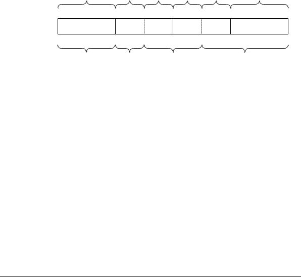
The RTCPeriphID0-3 registers are four, 8-bit registers that span address locations 0xFE0 to 0xFEC. The registers can conceptually be treated as a 32-bit register. Figure 3-1 shows the bit assignments for the RTCPeriphID0-3 registers.
Actual register bit assignment
Configuration |
|
Revision |
Designer 1 Designer 0 |
|
Part |
Part |
|
||||
|
number |
number 1 |
number 0 |
|
|||||||
7 |
0 |
7 |
4 |
3 |
0 |
7 |
4 |
3 |
0 |
7 |
0 |
31 |
24 23 |
20 19 |
16 15 |
12 11 |
8 |
7 |
0 |
||||
Configuration |
|
Revision |
|
Designer |
|
|
|
Part number |
|
||
|
|
number |
|
|
|
|
|
|
|
|
|
Conceptual register bit assignment
Figure 3-1 Peripheral identification register bit assignment
The read-only registers provide the following options of the peripheral, as shown in
Table 3-10.
|
|
Table 3-10 Read-only registers |
|
|
|
Bits |
Assignment |
Description |
|
|
|
11:0 |
Part number |
Identifies the peripheral, using the three-digit product code 0x031. |
|
|
|
19:12 |
Designer ID |
Gives the designer identification. ARM Limited is 0x41 (ASCII A). |
|
|
|
23:20 |
Revision |
Is the revision number of the peripheral. The revision number |
|
|
starts from 0. |
|
|
|
31:24 |
Configuration |
Is the configuration option of the peripheral. The configuration |
|
|
value is 0. |
|
|
|
3-8 |
Copyright © 2001 ARM Limited. All rights reserved. |
ARM DDI 0224B |