


Chapter 2
Functional Overview
This chapter describes the major functional blocks of the ARM PrimeCell Real Time Clock (PL031). It contains the following sections:
•ARM PrimeCell Real Time Clock (PL031) overview on page 2-2
•PrimeCell RTC functional description on page 2-5
•PrimeCell RTC operation on page 2-9.
ARM DDI 0224B |
Copyright © 2001 ARM Limited. All rights reserved. |
2-1 |

Functional Overview
2.1ARM PrimeCell Real Time Clock (PL031) overview
The ARM PrimeCell RTC (PL031) comprises:
•an AMBA APB interface
•a 32-bit counter
•a 32-bit match register
•a 32-bit comparator.
The CPU reads and writes data, and control and status information through the AMBA APB interface.
The 32-bit counter is incremented on successive rising edges of the input clock CLK1HZ. Counting in one second intervals is achieved by using a 1Hz clock signal for CLK1HZ. The counter is free-running and cannot be loaded. On reset, the counter:
•counts up from one
•reaches the maximum value, 0xFFFFFFFF
•wraps around to zero and continues incrementing.
RTC is loaded or updated by writing to the load register, RTCLR.
Reading the data register, RTCDR, gives the current value of the RTC.
The match register is programmed by writing to RTCMR. The counter and match values are compared in a comparator. When both values are equal, the interrupt RTCINTR is asserted HIGH. The CPU can use the interrupt to implement a basic time alarm function. The interrupt is cleared by writing any data value to the interrupt clear register RTCICR. The value in the match register can be read at any time.
The interrupt RTCINTR can be masked by writing to the interrupt match set or clear register, RTCIMSC. The raw status of the interrupt can be obtained by reading the RTCRIS register, and the masked version can be read from the RTCMIS register.
Synchronization logic is implemented to prevent propagation of metastable values when reading RTCDR. This ensures the stability of the data, even at the point that the counter is incrementing.
2-2 |
Copyright © 2001 ARM Limited. All rights reserved. |
ARM DDI 0224B |
Functional Overview
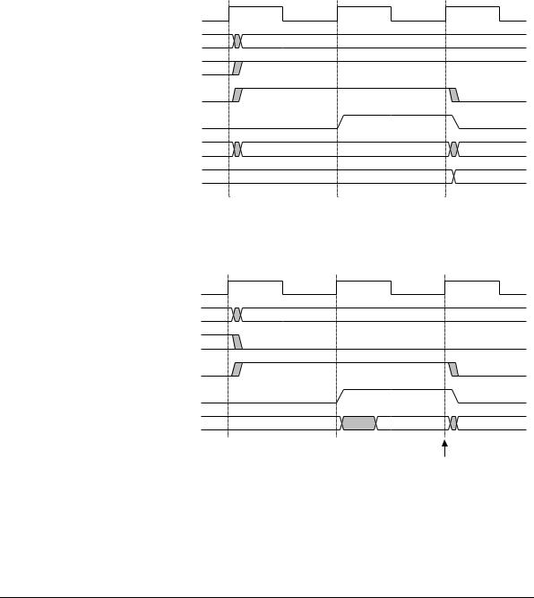
Figure 2-1 shows an AMBA APB write access.
PCLK
PADDR
PWRITE
PSEL
PENABLE
PWDATA |
DATA |
RTCLR/
DATA
RTCMR
Figure 2-1 AMBA APB write access
Figure 2-2 shows an AMBA APB read access.
PCLK
PADDR
PWRITE
PSEL
PENABLE
PRDATA |
DATA |
data sampled by APB bridge
Figure 2-2 AMBA APB read access
ARM DDI 0224B |
Copyright © 2001 ARM Limited. All rights reserved. |
2-3 |
Functional Overview
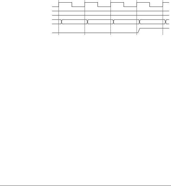
Figure 2-3 shows the interrupt generation when the current RTC value (RTCDR) value equals the match register value.
CLK1HZ
RTCMR 0x00000004
RTCDR |
0x00000002 |
0x00000003 |
0x00000004 |
0x00000005 |
RTCINTR
Figure 2-3 Interrupt generation
2-4 |
Copyright © 2001 ARM Limited. All rights reserved. |
ARM DDI 0224B |