
- •Introduction
- •1.1 About the ARM PrimeCell Real Time Clock (PL031)
- •1.1.1 Features of the PrimeCell RTC
- •Functional Overview
- •2.1 ARM PrimeCell Real Time Clock (PL031) overview
- •2.2 PrimeCell RTC functional description
- •2.2.1 AMBA APB interface
- •2.2.2 Register block
- •2.2.3 Control block
- •2.2.4 Update block
- •2.2.5 Synchronization block
- •2.2.6 Counter block
- •2.2.7 Test register and logic
- •2.3 PrimeCell RTC operation
- •2.3.1 Interface reset
- •2.3.2 Clock signals
- •2.3.3 PrimeCell RTC operation
- •Programmer’s Model
- •3.1 About the programmer’s model
- •3.2 Summary of PrimeCell RTC registers
- •3.3 General registers
- •3.3.1 Data register, RTCDR
- •3.3.2 Match register, RTCMR
- •3.3.3 Load register, RTCLR
- •3.3.4 Control register, RTCCR
- •3.3.5 Interrupt mask set or clear register, RTCIMSC
- •3.3.6 Raw interrupt status, RTCRIS
- •3.3.7 Masked interrupt status, RTCMIS
- •3.3.8 Interrupt clear register, RTCICR
- •3.4.1 RTCPeriphID0 register
- •3.4.2 RTCPeriphID1 register
- •3.4.3 RTCPeriphID2 register
- •3.4.4 RTCPeriphID3 register
- •3.5.1 RTCPCellID0 register
- •3.5.2 RTCPCellID1 register
- •3.5.3 RTCPCellID2 register
- •3.5.4 RTCPCellID3 register
- •3.6 Interrupts
- •Programmer’s Model for Test
- •4.1 PrimeCell RTC test harness overview
- •4.2 Scan testing
- •4.3 Test registers
- •4.3.1 Integration test control register, RTCITCR
- •4.3.2 Integration test input read or set register, RTCITIP
- •4.3.3 Integration test output read or set register, RTCITOP
- •4.3.4 Test offset register, RTCTOFFSET
- •4.3.5 Test count register, RTCTCOUNT
- •4.4 Integration testing of block inputs
- •4.5 Integration testing of block outputs
- •4.6 Integration test summary
- •A.1 AMBA APB signals
- •A.2 On-chip signals

Programmer’s Model for Test
4.5Integration testing of block outputs
This section describes the integration testing for the block intra-chip output. There are no primary outputs from the PrimeCell RTC.
4.5.1Intra-chip outputs
Use this test for the RTCINTR output.
When you run integration tests with the PrimeCell RTC in a standalone test setup:
•Write a 1 to the ITEN bit in the integration test control register. This selects the test path from the RTCITOP register to the intra-chip output signal.
•Write a 1 and then a 0 to the RTCITOP register bit, and read the same register bit to verify that the value written is read out.
When you run integration tests with the PrimeCell RTC as part of an integrated system:
•Write a 1 to the ITEN bit in the integration control register. This selects the test path from the RTCITOP register bit to the intra-chip output signal.
•Write a 1 and then a 0 to the RTCITOP register bit to toggle the signal connections between the interrupt controller and the PrimeCell RTC. Read from the internal test registers of the interrupt controller to verify that the value written into the RTCITOP register bit is read out through the PrimeCell RTC.
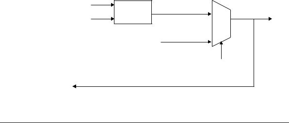
Figure 4-2 shows the implementation details of the output integration test harness for intra-chip outputs.
APB
RTCITOP[0]
Register
PCLK
RTCINTR
from PrimeCell RTC core
ITEN
To APB interface
Figure 4-2 Output integration test harness, intra-chip outputs
ARM DDI 0224B |
Copyright © 2001 ARM Limited. All rights reserved. |
4-7 |