

ARM ELF
3 GENERIC 32-BIT ELF
3.1 Introduction
Section 3 of this specification describes the object file format called ELF (Executable and Linking Format). There are three main types of object files:
A re-locatable file holds code and data suitable for linking with other object files to create an executable or a shared object file.
An executable file holds a program suitable for execution.
A shared object file holds code and data suitable for linking in two contexts. First, the link editor may process it with other re-locatable and shared object files to create another object file. Second, the dynamic linker combines it with an executable file and other shared objects to create a process image.
Created by an assembler or compiler and link editor, object files are binary representations of programs intended to execute directly on a processor. Programs that require other abstract machines are excluded.
After the introductory material, this section focuses on the file format and how it pertains to building programs. Subsections 3.7 onwards describe those parts of the object file containing the information necessary to execute a program.
3.1.1 File Format
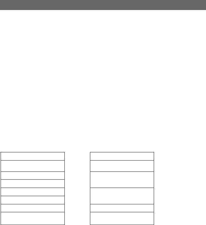
Object files participate in program linking (building a program) and program execution (running a program). For convenience and efficiency, the object file format provides parallel views of a file’s contents, reflecting the differing needs of these activities. Figure 3-1 below shows an object file’s organization.
Figure 3-1, Object file format
Linking View
ELF Header
Program Header Table
optional
Section 1
…
Section n
…
…
Section Header Table
Execution View
ELF Header
Program Header Table
Segment 1
Segment 2
…
Section Header Table
optional
An ELF header resides at the beginning and holds a road map describing the file’s organization. Sections hold the bulk of object file information for the linking view: instructions, data, symbol table, relocation information, and so on. Descriptions of special sections appear later in this section. Subsections 3.7 onwards describe segments and the program execution view of the file.
SWS ESPC 0003 B-02 |
Page 6 of 42 |
ARM ELF
A program header table, if present, tells the system how to create a process image. Files used to build a process image (execute a program) must have a program header table; re-locatable files do not need one. A section header table contains information describing the file’s sections. Every section has an entry in the table; each entry gives information such as the section name, the section size, and so on. Files used during linking must have a section header table; other object files may or may not have one.
Note Although the figure shows the program header table immediately after the ELF header, and the section header table following the sections, actual files may differ. Moreover, sections and segments have no specified order. Only the ELF header has a fixed position in the file.
3.1.2 Data Representation
As described here, the object file format supports various processors with 8-bit bytes and 32-bit architectures. Nevertheless, it is intended to be extensible to larger (or smaller) architectures. Object files therefore represent some control data with a machine-independent format, making it possible to identify object files and interpret their contents in a common way. Remaining data in an object file use the encoding of the target processor, regardless of the machine on which the file was created.
Figure 3-2, 32-Bit Data Types
Name |
Size |
Alignment |
Purpose |
|
|
|
|
Elf32_Addr |
4 |
4 |
Unsigned program address |
|
|
|
|
Elf32_Half |
2 |
2 |
Unsigned medium integer |
|
|
|
|
Elf32_Off |
4 |
4 |
Unsigned file offset |
|
|
|
|
Elf32_Sword |
4 |
4 |
Signed large integer |
|
|
|
|
Elf32_Word |
4 |
4 |
Unsigned large integer |
|
|
|
|
unsigned char |
1 |
1 |
Unsigned small integer |
|
|
|
|
All data structures that the object file format defines follow the natural size and alignment guidelines for the relevant class. If necessary, data structures contain explicit padding to ensure 4-byte alignment for 4-byte objects, to force structure sizes to a multiple of 4, and so on. Data also have suitable alignment from the beginning of the file. Thus, for example, a structure containing an Elf32_Addr member will be aligned on a 4-byte boundary within the file.
For portability reasons, ELF uses no bit fields.
3.1.3 Character Representations
This section describes the default ELF character representation and defines the standard character set used for external files that should be portable among systems. Several external file formats represent control information with characters. These single-byte characters use the 7-bit ASCII character set. In other words, when the ELF interface document mentions character constants, such as, ‘/’ or ‘\n’ their numerical values should follow the 7-bit ASCII guidelines. For the previous character constants, the single-byte values would be 47 and 10, respectively.
Character values outside the range of 0 to 127 may occupy one or more bytes, according to the character encoding. Applications can control their own character sets, using different character set extensions for different languages as appropriate. Although TIS-conformance does not restrict the character sets, they generally should follow some simple guidelines:
Character values between 0 and 127 should correspond to the 7-bit ASCII code. That is, character sets with encodings above 127 should include the 7-bit ASCII code as a subset.
SWS ESPC 0003 B-02 |
Page 7 of 42 |