

Fieldbus Appendix - ANYBUS®-S Modbus RTU
DOC. ABS-APPENDIX-RTU Rev 1.00
2003-04-28
3.3 Switches
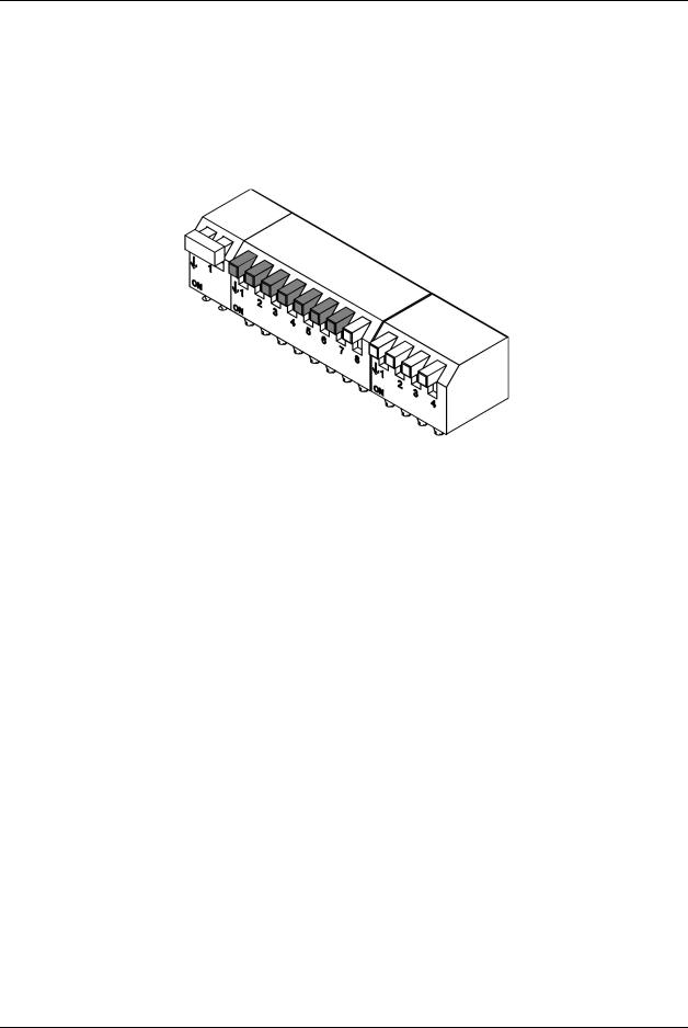
3.3.1 Node ID Switch
The Node ID must be configured before power on - it is not possible to change the node ID during operation. The Node ID is set in binary format. Valid settings range from 1-127 (247 with mailbox messages). Setting 0 is dedicated for SW configuration via Mailbox message in the INIT sequence.
(ON=1, OFF=0) 1 = MSB, 7 = LSB
Figure 3: Node ID switch
Binary value |
Dip 1 to Dip 7 |
|
|
|
|
0000000 |
Setting not valid |
|
|
00000001 |
1 |
|
|
00000010 |
2 |
|
|
00000011 |
3 |
|
|
... |
... |
|
|
... |
... |
|
|
11111111 |
127 |
|
|
Table 5: Binary value; node ID
The full-extended Node address settings will only be available through the mailbox interface (see section 6.2).
Note: When all the switches are set to the “OFF”- position, this is indicated with the LED “HW Setting status” turning red. If no mailbox message is used for setting the baudrate, address and parity, the module initiates the baudrate to 19,2 kBit/s with no parity. It will then only respond to broadcast messages.
HMS INDUSTRIAL NETWORKS AB |
11 |
Fieldbus Appendix - ANYBUS®-S Modbus RTU DOC. ABS-APPENDIX-RTU Rev 1.00 2003-04-28
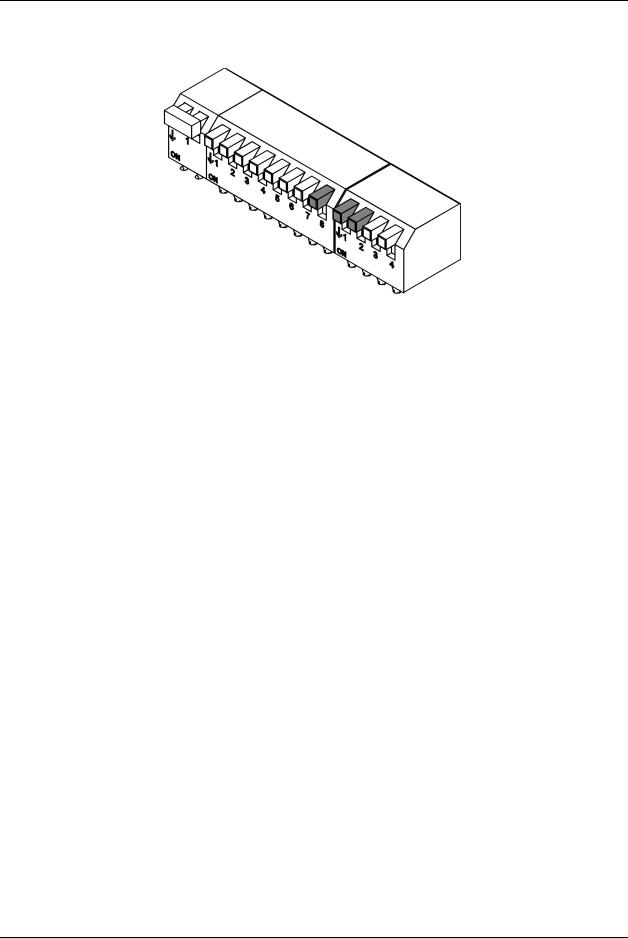
3.3.2 Baudrate switch
The baudrate must be set before power on - it is not possible to change the baud rate during operation.
(ON=1, OFF=0) 8 = MSB, 2 = LSB
Figure 4: Baudrate switch
Binary value |
Dip 8, Dip 1, Dip 2 |
|
|
|
|
000 |
Setting not valid |
|
|
001 |
1200 |
|
|
010 |
2400 |
|
|
011 |
4800 |
|
|
100 |
9600 |
|
|
101 |
19200 (Default on RTU) |
|
|
110 |
38400 |
|
|
111 |
57600 |
|
|
Table 6: Binary value; baudrate
These settings are also available through the mailbox interface.
12 |
HMS INDUSTRIAL NETWORKS AB |
Fieldbus Appendix - ANYBUS®-S Modbus RTU
DOC. ABS-APPENDIX-RTU Rev 1.00
2003-04-28
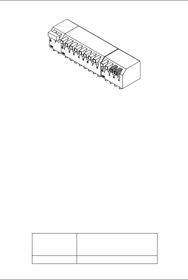
3.3.3 Parity switch
The parity must be set before power on - it is not possible to change it during operation
(ON=1, OFF=0) 3 = MSB, 4 = LSB
|
Figure 5: Parity switch |
|
|
|
|
Binary value |
|
Dip 3, Dip 4 |
|
|
|
|
|
|
00 |
|
Setting not valid |
|
|
|
01 |
|
None (Default on RTU) |
|
|
|
10 |
|
Even |
|
|
|
11 |
|
Odd |
|
|
|
Table 7: Binary value; parity
These settings are also available from the mailbox interface.
Note:
•If parity is used, one stop bit is used.
•If parity is not used, two stop bits are used.
3.3.4 Termination
If RS485 is used, the end nodes in a Modbus RTU network have to be terminated in order to avoid reflections on the bus line. The AnyBus-S Modbus RTU module is equipped with a termination switch as to accomplish this in an easy way. If the module is used as the first or last module in a network, the termination switch has to be in the “ON” position. Otherwise the switch has to be in the “OFF” position.
PLEASE NOTE: If an external termination connector is used, the switch must be in the “OFF” position.
Termination switch ON Bus termination enabled. If the module is the last or first module, the bus termination has to be set on, or an external termination connector has to be used
Termination switch OFF Bus termination disabled
Table 8: Termination
HMS INDUSTRIAL NETWORKS AB |
13 |