


Fieldbus Appendix - ANYBUS®-S Modbus RTU
DOC. ABS-APPENDIX-RTU Rev 1.00
2003-04-28
8 Electrical characteristics
8.1 Supply voltage
This product requires a power supply of ±5 V ±5%
8.2 Maximum current consumption
The maximum current consumption is 450 mA total current consumption on the 5V BUS and 5 V Electronics.
8.3 PE Grounding
PE is connected via the fieldbus connector and the mounting hole.
8.4 Application interface pin configuration
The table below describes the general pin configuration for the Application interface
Contact Pin |
Description |
Symbol |
Min |
Type |
Max |
Unit |
|
|
|
|
|
|
|
1 |
+5V BUS |
VCC |
4.75 |
5.0 |
5.25 |
V |
|
|
|
|
|
|
|
|
Bus Electronic |
IIN |
- |
70 |
90 |
mA |
|
|
|
|
|
|
|
2 |
GNDBUS Ground |
|
|
|
|
|
|
|
|
|
|
|
|
3-4 |
No Connection |
|
|
|
|
|
|
|
|
|
|
|
|
5 |
+5V Power |
VCC |
4.5 |
5.0 |
5.5 |
V |
|
|
|
|
|
|
|
|
Electronic |
IIN |
- |
100 |
120 |
mA |
|
|
|
|
|
|
|
6 |
GND Ground |
|
|
|
|
|
|
|
|
|
|
|
|
7-31 |
Depending on Interface, |
|
|
|
|
|
|
please see tables below |
|
|
|
|
|
33-34 |
|
|
|
|
|
|
|
|
|
|
|
|
|
|
|
|
|
|
|
|
32 |
RES IN |
VIH |
0.7 VCC |
|
|
V |
|
|
|
|
|
|
|
|
Reset |
VIL |
|
|
0.3 VCC |
V |
|
|
|
|
|
|
|
|
(pulse duration) |
tW |
1.0 |
|
|
µS |
|
|
|
|
|
|
|
Table 29: Application interface pin configuration
HMS INDUSTRIAL NETWORKS AB |
31 |

Fieldbus Appendix - ANYBUS®-S Modbus RTU DOC. ABS-APPENDIX-RTU Rev 1.00 2003-04-28
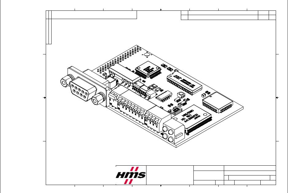
9 Mechanical specification
This chapter includes drawings of the AnyBus-S Modbus RTU module for overview and mechanical design. The tolerances for all measurements are ± 0.1 mm unless otherwise stated.
For further information regarding the AnyBus-S module, refer to the AnyBus-S Design Guide.
9.1 Mechanical drawings in this chapter
•AnyBus-S Modbus RTU Angled configuration 3-D view
•AnyBus-S Modbus RTU Angled configuration Top view
•AnyBus-S Modbus RTU Angled configuration Frontand side view
•AnyBus-S Modbus RTU Angled configuration PCB connection points
32 |
HMS INDUSTRIAL NETWORKS AB |
AB NETWORKS INDUSTRIAL HMS
33
8 |
7 |
6 |
THE INFORMATION CONTAINED IN THIS DRAWING IS THE SOLE PROPERTY OF
HMS INDUSTRIAL NETWORKS AB ANY REPRODUCTION IN PART OR WHOLE WITHOUT THE WRITTEN PERMISSION OF HMS INDUSTRIAL NETWORKS AB IS PROHIBITED.
D
7: Figure |
|
AngledRTUModbusS-AnyBus |
C |
viewD-3configuration |
B |
|
A |
8 |
7 |
6 |
5 |
4 |
Pos.
HMS Industrial Networks AB
Pilefeltsgatan 95-93
S-302 50 Halmstad
Tel: +46 (0)35 - 17 29 00
Fax: +46 (0)35 - 17 29 09
5 |
4 |
3 |
2 |
1 |
Revisions |
|
Date Sign |
D
C
B
A
Title: ABS Modbus RTU ISO-view
UNLESS OTHERWISE SPECIFIED |
Document nr: |
XXXXXXXXXXXXX |
|
||
DIMENSIONS ARE IN |
|
|
|
|
|
MILLIMETERS. |
|
SIZE |
CAD FILE: |
REV. |
|
TOLERANCE: + / - 0,1 |
|
A4L |
ABS Modbus RTU |
1.0 |
|
DATE 2001-06-08 |
Sign: |
|
|
PCB nr: 4125-110 |
SHEET 1 OF 4 |
NiE |
SCALE 2:1 |
||||
3 |
|
|
2 |
|
1 |
ABS .DOC |
- Appendix Fieldbus |
00.1 Rev RTU-APPENDIX- 28-04-2003 |
RTU Modbus S-ANYBUS® |
Fieldbus Appendix - ANYBUS®-S Modbus RTU DOC. ABS-APPENDIX-RTU Rev 1.00 2003-04-28
|
D |
C |
|
B |
|
A |
|
REV |
OF4 |
|
|
Sign |
|
|
|
|
|
|
|
||
|
|
|
|
|
|
|
|
1.0 |
|
|
|
|
|
|
|
|
|
|
. |
|
|
1 |
Date |
15,9 |
8,1 |
|
|
Top-view |
XXXXXXXXXXXXX |
FILE: RTUModbus |
4125nr:PCB -110 SHEET 2 |
1 |
2 |
|
13,8 |
|
|
ABSModbusRTU |
Documentnr: |
A4L |
SCALE2:1 |
2 |
|
|
Revisions |
|
|
13,6 |
9,7 |
Title: |
OTHERWISE |
CAD ABS |
08-06-2001 |
|
|
|
|
0,1-/+ |
|
||||||
|
|
|
|
|
|
|
|
SIZE |
|
|
|
|
|
|
|
6,57 |
|
SPECIFIED |
|
NiE |
|
|
|
|
|
|
|
|
Sign: |
|
||
|
|
|
|
|
|
|
ARE IN |
|
|
|
3 |
|
|
|
|
7,16 |
|
UNLESS DIMENSIONS MILLIMETERS. TOLERANCE: |
DATE |
3 |
|
4 |
Pos. |
|
|
|
|
NetworksAB |
|
29 |
09 |
4 |
|
|
|
|
|
|
|
|
00 |
29 |
|
|
|
|
|
|
|
IndustrialHMS |
-9593 |
|
|
|
5 |
|
|
|
|
|
|
- |
5 |
||
|
|
|
|
|
Pilefeltsgatan Halmstad50302-S (0)35+46Tel: - (0)35+46Fax: |
|||||
|
|
|
|
|
9,44 |
|
|
17 |
17 |
|
|
|
|
|
|
|
|
|
|
||
78 6 |
SOLETHEISDRAWINGTHISINCONTAINEDINFORMATIONPROPERTY OF PARTINREPRODUCTIONANYABNETWORKSINDUSTRIALOR WHOLE WITHOUT ABNETWORKSINDUSTRIALHMSOFPERMISSIONWRITTENIS PROHIBITED. |
|
|
|
8,03 |
|
|
|
|
78 6 |
|
22,3 |
15,3 |
9,11 |
|
|
|
|
|||
|
|
|
|
|
|
|
|
|
|
|
|
|
|
|
|
0 |
|
|
|
|
|
|
THE HMS THE |
|
|
|
|
|
|
|
|
|
|
D |
C |
|
B |
|
A |
|
|
|
|
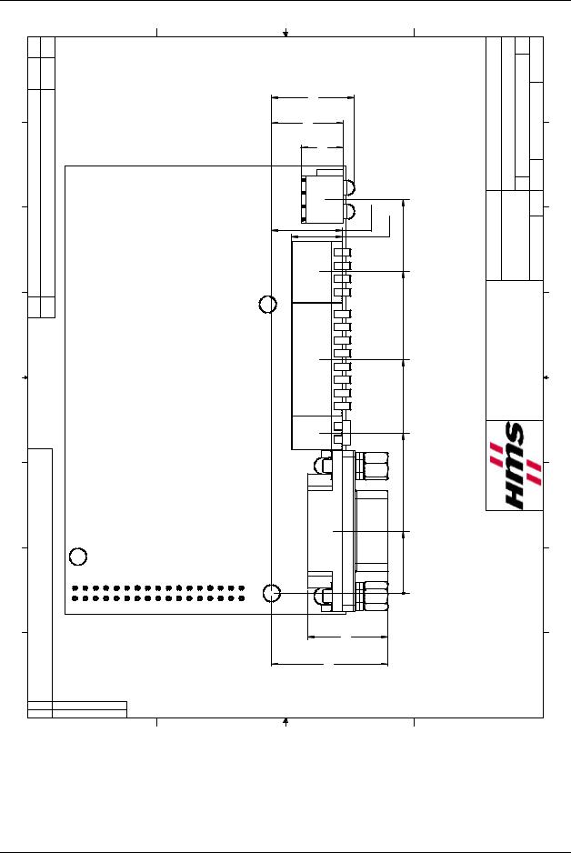
Figure 8: AnyBus-S Modbus RTU Angled configuration Top view
34 |
HMS INDUSTRIAL NETWORKS AB |
AB NETWORKS INDUSTRIAL HMS
35
8 |
7 |
6 |
5 |
4 |
3 |
2 |
1 |
THE INFORMATION CONTAINED IN THIS DRAWING IS THE SOLE PROPERTY OF |
|
Pos. |
Revisions |
|
Date Sign |
||
HMS INDUSTRIAL NETWORKS AB ANY REPRODUCTION IN PART OR WHOLE WITHOUT |
|
|
|||||
THE WRITTEN PERMISSION OF HMS INDUSTRIAL NETWORKS AB IS PROHIBITED.
|
D |
|
|
|
|
|
D |
|
30,8 |
6,5 |
21,7 |
11,7 |
9,2 |
|
|
|
25,0 |
|
|
|
4,6 |
|
|
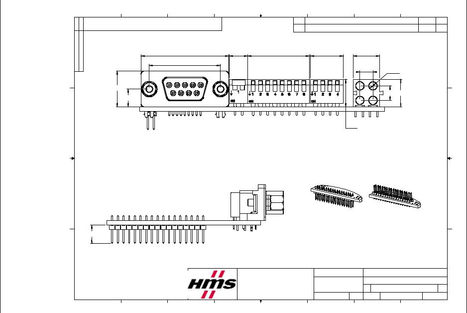
Figure |
|
|
|
|
2,9 |
|
|
12,6 |
|
|
|
|
|
|
|
9: |
|
|
|
|
5,08 |
9,7 |
|
|
|
|
|
|
|||
S-AnyBus |
6,3 |
|
|
|
|
||
|
|
|
|
|
|
||
Modbus |
C |
|
|
|
9,7 |
|
C |
|
|
|
|
|
|
|
Angled RTU |
|
|
|
|
|
|
|
|
|
|
-Frontconfiguration |
|
|
|
|
|
Application connector alternatives |
|
|||
|
B |
|
|
|
|
|
|
|
|
B |
|
|
|
|
|
|
|
|
|
|
|
side and |
|
|
|
|
|
Bottom side |
|
Top side |
|
|
6,4-12,2mm |
|
|
|
|
|
|
|
|
|
|
view |
|
|
|
|
|
|
|
|
|
|
|
|
|
|
|
|
|
|
|
|
|
|
A |
|
|
|
|
|
|
|
|
A |
|
|
|
|
HMS Industrial Networks AB |
|
Title: ABS Modbus RTU Front &side-view |
||||
|
|
|
|
Pilefeltsgatan 95-93 |
|
UNLESS OTHERWISE SPECIFIED |
Document nr: XXXXXXXXXXXXX |
|
||
|
|
|
|
|
DIMENSIONS ARE IN |
|
|
|
|
|
|
|
|
|
S-302 50 Halmstad |
|
MILLIMETERS. |
|
SIZE |
CAD FILE: |
REV. |
|
|
|
|
Tel: +46 (0)35 - 17 29 00 |
TOLERANCE: + / - 0,1 |
Sign: |
A4L |
ABS Modbus RTU |
1.0 |
|
|
|
|
|
Fax: +46 (0)35 - 17 29 09 |
DATE 2001-06-08 |
SCALE 2:1 PCB nr: 4125-110 |
SHEET 3 OF 4 |
|||
|
|
|
|
NiE |
||||||
|
8 |
7 |
6 |
5 |
4 |
3 |
|
|
2 |
1 |
ABS .DOC |
- Appendix Fieldbus |
00.1 Rev RTU-APPENDIX- 28-04-2003 |
RTU Modbus S-ANYBUS® |
Fieldbus Appendix - ANYBUS®-S Modbus RTU |
|
|
|
|
|
|
|
|
|||||||||
DOC. ABS-APPENDIX-RTU Rev 1.00 |
|
|
|
|
|
|
|
|
|
|
|
||||||
2003-04-28 |
|
|
|
|
|
|
|
|
|
|
|
|
|
|
|
||
|
Sign |
D |
|
|
|
C |
|
|
|
|
B |
|
A |
|
REV |
4OF |
|
|
|
|
|
|
|
|
|
|
|
|
|
|
|
|
|||
|
|
|
|
|
|
|
|
|
|
|
|
|
|
|
1.0 |
|
|
|
|
|
|
|
|
|
|
|
|
|
|
|
|
|
. |
|
|
1 |
Date |
|
|
|
|
|
|
|
|
|
|
|
|
|
|
SHEET 4 |
1 |
2 |
|
|
|
|
|
|
|
|
|
|
|
1,6 |
RTU PCB |
XXXXXXXXXXXXX |
FILE: ModbusRTU |
nr:PCB4125-110 |
2 |
|
|
|
|
|
|
|
|
|
|
|
ModbusABS |
Documentnr: |
SIZE |
SCALE1.5:1 |
|||
|
Revisions |
|
|
|
|
|
|
|
|
|
|
|
|
SPECIFIED |
CAD ABS |
|
|
|
|
|
|
|
A |
|
|
|
|
|
|
Title: |
A4L Sign: |
|
|||
|
|
|
|
|
|
|
|
|
|
|
|
|
|
|
|
NiE |
|
|
|
|
|
|
|
|
|
|
|
|
|
|
|
AREIN |
+ / - 0,1 |
2001-06-08 |
|
3 |
|
|
|
|
|
|
|
2,54 |
2,54 |
|
|
|
|
OTHERWISE |
3 |
||
|
|
|
|
|
|
|
0,9 |
|
8,17 |
|
IndustrialHMSNetworks AB |
UNLESS DIMENSIONS MILLIMETERS. TOLERANCE: |
DATE |
||||
5 4 |
Pos. |
|
|
|
|
3x3,2 |
|
|
|
|
86,0 |
A-A |
Pilefeltsgatan Halmstad50302-S -(0)35+46Tel: (0)35+46Fax: |
5 4 |
|||
|
|
|
|
|
|
|
|
|
|
|
|
|
5,55 |
|
|
|
|
|
|
|
|
|
|
|
|
|
|
|
|
|
|
9395290017 091729- |
|
||
78 6 |
ISDRAWINGTHISINCONTAINEDINFORMATIONTHE SOLE PROPERTY OF INREPRODUCTIONANYABNETWORKSINDUSTRIALPART OR WHOLE WITHOUT NETWORKSINDUSTRIALHMSOFPERMISSIONWRITTENAB IS PROHIBITED. |
2,0 |
37,2 |
2,0 |
54,0 |
A5,8 |
0,75 |
|
6,3 |
12,9 |
2,0 |
|
|
|
|
|
78 6 |
0 |
14,3 |
|
|
|
|
|
|||||||||||
|
|
|
|
|
0,8 |
|
|
|
0,8 |
|
|
|
|
|
|
|
|
|
|
|
|
|
|
|
|
|
|
|
0,2 |
|
0,7 |
|
|
|
|
|
|
|
|
|
|
|
|
|
|
|
0 |
|
0 |
|
|
|
|
|
|
|
|
|
|
|
|
|
|
|
|
|
0,4 |
|
|
|
|
|
|
|
|
|
|
|
|
|
|
|
0,1 |
|
|
|
|
|
|
|
THE HMS THE |
|
|
|
|
|
|
|
|
|
|
|
|
|
|
|
|
|
|
D |
|
|
|
C |
|
|
|
|
B |
|
A |
|
|
|
|
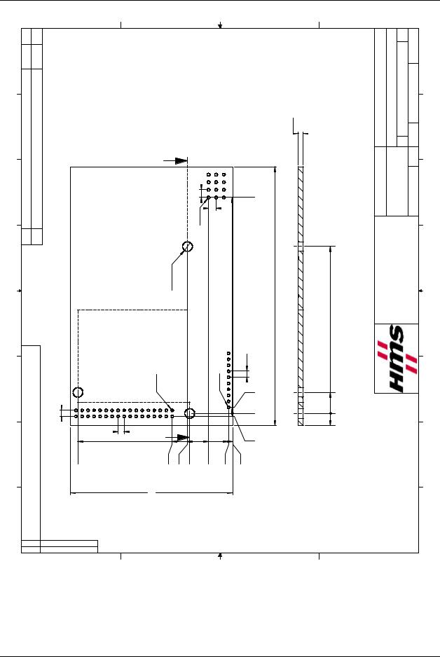
Figure 10: AnyBus-S Modbus RTU Angled configuration PCB connection points
36 |
HMS INDUSTRIAL NETWORKS AB |

Fieldbus Appendix - ANYBUS®-S Modbus RTU
DOC. ABS-APPENDIX-RTU Rev 1.00
2003-04-28
10 List of Figures
Figure 1: AnyBus-S Modbus RTU module. . . . . . . . . . . . . . . . . . . . . . . . . . . . . . . . . . . . . . . . 7 Figure 2: AnyBus-S Access Methods . . . . . . . . . . . . . . . . . . . . . . . . . . . . . . . . . . . . . . . . . . . . 8 Figure 3: Node ID switch . . . . . . . . . . . . . . . . . . . . . . . . . . . . . . . . . . . . . . . . . . . . . . . . . . . . 11 Figure 4: Baudrate switch . . . . . . . . . . . . . . . . . . . . . . . . . . . . . . . . . . . . . . . . . . . . . . . . . . . . 12 Figure 5: Parity switch . . . . . . . . . . . . . . . . . . . . . . . . . . . . . . . . . . . . . . . . . . . . . . . . . . . . . . 13 Figure 6: AnyBus-S LED´s, angle mounted . . . . . . . . . . . . . . . . . . . . . . . . . . . . . . . . . . . . . . 14 Figure 7: AnyBus-S Modbus RTU Angled configuration 3-D view . . . . . . . . . . . . . . . . . . . 33 Figure 8: AnyBus-S Modbus RTU Angled configuration Top view . . . . . . . . . . . . . . . . . . . 34 Figure 9: AnyBus-S Modbus RTU Angled configuration Frontand side view . . . . . . . . . . 35 Figure 10: AnyBus-S Modbus RTU Angled configuration PCB connection points . . . . . . . 36
HMS INDUSTRIAL NETWORKS AB |
37 |

Fieldbus Appendix - ANYBUS®-S Modbus RTU DOC. ABS-APPENDIX-RTU Rev 1.00 2003-04-28
11 List of Tables
Table 1: D-SUB . . . . . . . . . . . . . . . . . . . . . . . . . . . . . . . . . . . . . . . . . . . . . . . . . . . . . . . . . . . . . 9 Table 2: Screw terminal . . . . . . . . . . . . . . . . . . . . . . . . . . . . . . . . . . . . . . . . . . . . . . . . . . . . . . . 9 Table 3: 2 mm connector . . . . . . . . . . . . . . . . . . . . . . . . . . . . . . . . . . . . . . . . . . . . . . . . . . . . . 10 Table 4: Supported baudrates by Modbus RTU . . . . . . . . . . . . . . . . . . . . . . . . . . . . . . . . . . . 10 Table 5: Binary value; node ID . . . . . . . . . . . . . . . . . . . . . . . . . . . . . . . . . . . . . . . . . . . . . . . . 11 Table 6: Binary value; baudrate. . . . . . . . . . . . . . . . . . . . . . . . . . . . . . . . . . . . . . . . . . . . . . . . 12 Table 7: Binary value; parity . . . . . . . . . . . . . . . . . . . . . . . . . . . . . . . . . . . . . . . . . . . . . . . . . . 13 Table 8: Termination . . . . . . . . . . . . . . . . . . . . . . . . . . . . . . . . . . . . . . . . . . . . . . . . . . . . . . . . 13 Table 9: LED descriptions . . . . . . . . . . . . . . . . . . . . . . . . . . . . . . . . . . . . . . . . . . . . . . . . . . . . 14 Table 10: LED 1 Indications . . . . . . . . . . . . . . . . . . . . . . . . . . . . . . . . . . . . . . . . . . . . . . . . . . 14 Table 11: LED 2 Indications . . . . . . . . . . . . . . . . . . . . . . . . . . . . . . . . . . . . . . . . . . . . . . . . . . 15 Table 12: LED 3 Indications . . . . . . . . . . . . . . . . . . . . . . . . . . . . . . . . . . . . . . . . . . . . . . . . . . 15 Table 13: LED 4 Indications . . . . . . . . . . . . . . . . . . . . . . . . . . . . . . . . . . . . . . . . . . . . . . . . . . 15 Table 14: Watchdog LED . . . . . . . . . . . . . . . . . . . . . . . . . . . . . . . . . . . . . . . . . . . . . . . . . . . . 15 Table 15: Supported Exception Codes. . . . . . . . . . . . . . . . . . . . . . . . . . . . . . . . . . . . . . . . . . . 17 Table 16: DPRAM IN/OUT data areas . . . . . . . . . . . . . . . . . . . . . . . . . . . . . . . . . . . . . . . . . . 18 Table 17: Mailbox area . . . . . . . . . . . . . . . . . . . . . . . . . . . . . . . . . . . . . . . . . . . . . . . . . . . . . . 19 Table 18: FB_INIT . . . . . . . . . . . . . . . . . . . . . . . . . . . . . . . . . . . . . . . . . . . . . . . . . . . . . . . . . 20 Table 19: Command and response: FB_INIT . . . . . . . . . . . . . . . . . . . . . . . . . . . . . . . . . . . . . 20 Table 20: Run state telegram : GET_MB_COM_SETTINGS . . . . . . . . . . . . . . . . . . . . . . . . 23 Table 21: Command and response: Run state telegram; GET_MB_COM_SETTINGS. . . . . 23 Table 22: Run state telegram: GET_COM_STATUS . . . . . . . . . . . . . . . . . . . . . . . . . . . . . . . 24 Table 23: Command and response: Run state telegram; GET_COM_STATUS. . . . . . . . . . . 24 Table 24: Fieldbus specific area . . . . . . . . . . . . . . . . . . . . . . . . . . . . . . . . . . . . . . . . . . . . . . . 26 Table 25: Control area . . . . . . . . . . . . . . . . . . . . . . . . . . . . . . . . . . . . . . . . . . . . . . . . . . . . . . . 26 Table 26: Command and response layout; Initalization example . . . . . . . . . . . . . . . . . . . . . . 27 Table 27: Command and response layout; Data To Network . . . . . . . . . . . . . . . . . . . . . . . . . 28 Table 28: Command and response layout; Data From Network . . . . . . . . . . . . . . . . . . . . . . . 29 Table 29: Application interface pin configuration. . . . . . . . . . . . . . . . . . . . . . . . . . . . . . . . . . 31
38 |
HMS INDUSTRIAL NETWORKS AB |
If you have any comments about this documentation, please take a few minutes to fill out this form, and let us know about your opinions. These comments will help us improve our work, and make us aware of what customers of our products may find good, faulty or even missing.
Document title and revision:_________________________________________________________________
Your name and company:____________________________________________________________________
Phone:___________________________________________________________________________________
E-mail:___________________________________________________________________________________
Comments:
Text and illustrations:
_________________________________________________________________________________________
_________________________________________________________________________________________
_________________________________________________________________________________________
_________________________________________________________________________________________
What information is missing or unclear?:
_________________________________________________________________________________________
_________________________________________________________________________________________
_________________________________________________________________________________________
_________________________________________________________________________________________
Other comments:
_________________________________________________________________________________________
_________________________________________________________________________________________
_________________________________________________________________________________________
_________________________________________________________________________________________
Send your comments to: |
You may also mail or fax your comments: |
HMS Industrial Networks AB |
E-mail: support@hms-networks.com |
Support Department |
Fax: +46 (0)35 172909 |
Pilefeltsgatan 93-95 |
|
302 50 Halmstad |
|
SWEDEN