

FIELDBUS APPENDIX - ANYBUS-S MODBUS PLUS DOC. NO ABS-MBP-1.31
2002-08-09
3
4
5
6
7
8 |
|
: 9 |
THE INFORMATION CONTAINED IN THIS DRAWING IS THE SOLE PROPERTY OF HMS INDUSTRIAL NETWORKS AB. ANY REPRODUCTION IN PART OR WHOLE WITHOUT THE WRITTEN PERMISSION OF HMS INDUSTRIAL NETWORKS AB IS PROHIBITED. |
F |
E |
|
|
|
|
D |
|
|
C |
|
|
|
|
|
|
|
|
|
|
|
HMS Industrial Networks AB |
Pilefeltsgatan 93-95 |
S-302 50 Halmstad |
Tel: +46 (0)35 - 17 29 00 |
Fax: +46 (0)35 - 17 29 09 |
|
|
|
A |
|
|
|
|
1,6 |
|
|
|
|
SPECIFIED |
|
|
|
|
|
2,54 |
|
|
71,8 |
|
|
|
|
UNLESS OTHERWISE |
DIMENSIONS ARE IN |
MILLIMETERS. TOLERANCE: +/- 0,1 |
|
|
|
|
2,54 |
|
|
|
|
|
|
|
|
|
|
|
|
0,9 |
|
|
|
|
|
|
|
|
|
|
|
|
|
|
|
|
|
55,5 |
|
|
|
|
|
|
|
3,2 |
|
|
|
|
|
|
|
|
|
|
|
|
|
3x |
|
|
|
|
86,0 |
A-A |
|
|
|
|
|
|
|
0,8 |
|
|
0,8 |
|
2,0 |
|
|
|
|
|
|
|
|
|
|
|
|
|
2,0 |
7,0 |
|
|
|
|
|
|
2,0 |
A |
|
|
|
|
0 |
0 |
|
|
|
|
|
|
|
|
|
|
|
1,0 |
4,0 |
|
|
|
|
|
|
|
|
2,0 |
|
|
|
|
|
|
|
|
|
|
|
|
|
|
|
|
|
|
|
|
|
|
|
|
|
|
37,3 |
5,8 |
0,75 |
0 |
6,2 |
12,9 |
14,3 |
|
|
|
|
|
|
|
|
54,0 |
|
|
|
|
|
|
|
|
|
|
|
|
F |
E |
|
|
|
|
D |
|
|
C |
|
|
|
|
3
4
5
6
7
8
9
:
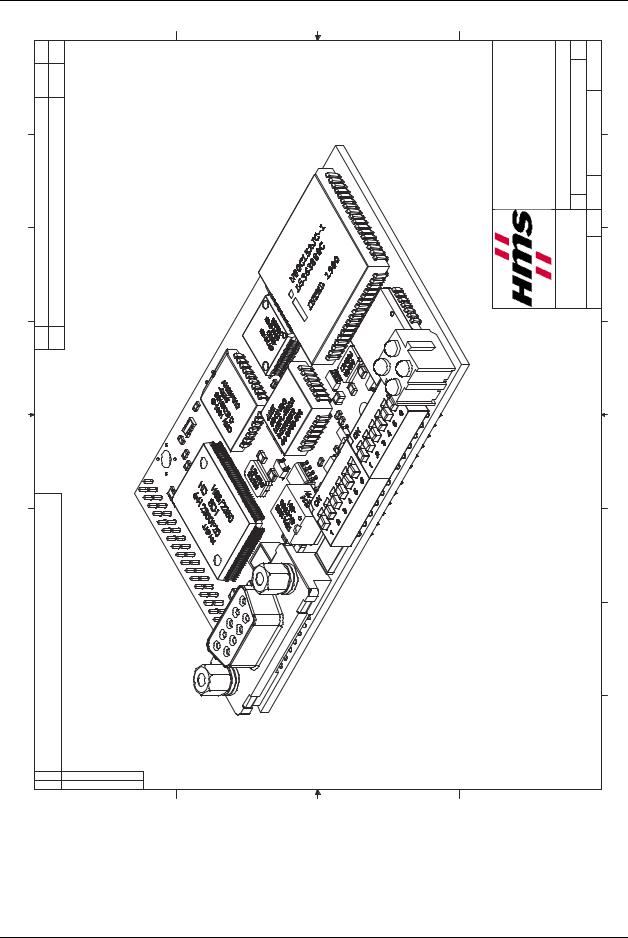
Figure 8: AnyBus-S Modbus Plus Angled PCB view
32 |
HMS INDUSTRIAL NETWORKS AB |
FIELDBUS APPENDIX - ANYBUS-S MODBUS PLUS DOC. NO ABS-MBP-1.31 2002-08-09
F |
E |
D |
C |
3
4
5
6
7
: 9 8 |
|
THE INFORMATION CONTAINED IN THIS DRAWING IS THE SOLE PROPERTY OF HMS INDUSTRIAL NETWORKS AB. ANY REPRODUCTION IN PART OR WHOLE WITHOUT THE WRITTEN PERMISSION OF HMS INDUSTRIAL NETWORKS AB IS PROHIBITED. |
|
||
|
HMS Industrial Networks AB |
Pilefeltsgatan 93-95 S-302 50 Halmstad Tel: +46 (0)35 - 17 29 00 Fax: +46 (0)35 - 17 29 09 |
4 3 |
|
UNLESS OTHERWISE SPECIFIED DIMENSIONS ARE IN MILLIMETERS. TOLERANCE: +/- 0,1 |
5 |
6
7
8
9
:
F |
E |
D |
C |
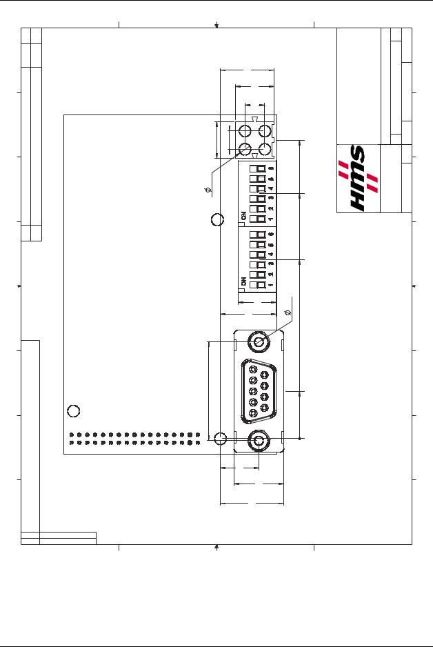
Figure 9: AnyBus-S Modbus Plus Straight 3-D view
HMS INDUSTRIAL NETWORKS AB |
33 |
FIELDBUS APPENDIX - ANYBUS-S MODBUS PLUS |
|
|
|
|
|
|
|
|
|
|
|
|||
DOC. NO ABS-MBP-1.31 |
|
|
|
|
|
|
|
|
|
|
|
|
|
|
2002-08-09 |
|
|
|
|
|
|
|
|
|
|
|
|
|
|
|
F |
E |
|
|
D |
|
|
|
C |
|
|
|
|
|
4 3 |
|
|
|
|
|
|
AB |
93Pilefeltsgatan-95 |
Halmstad50302-S |
-(0)35+46Tel:17 29 00 |
(0)35+46Fax:- 17 29 09 |
|
|
4 3 |
|
9,2 |
4,6 |
|
5,0 |
75,6 |
HIndustrialMS Networks |
|
|
||||||
|
|
|
|
13,6 |
|
|
|
|
|
|
|
|
|
|
|
|
|
|
|
9,7 |
|
|
|
|
|
|
|
|
|
|
|
2,9 |
|
|
|
|
|
|
|
|
SPECIFIED |
DIMENSIONSARE IN |
MILLIMETERS. TOLERANCE:+/- 0,1 |
|
5 |
|
|
|
|
62,1 |
|
|
|
|
UNLESSOTHERWISE |
5 |
|||
|
|
|
|
|
|
|
|
|
|
|
|
|
|
|
6 |
|
|
|
|
|
45,4 |
|
|
|
|
|
|
|
6 |
|
|
|
|
|
|
|
|
|
|
|
|
|
|
|
|
|
|
|
|
9,6 |
3,2 |
|
|
|
|
|
|
|
|
7 |
PROPERTYSOLETHEISDRAWINGTHISINCONTAINEDINFORMATIONTHE OF HMS WHOLEORPARTINREPRODUCTIONANYAB.NETWORKSINDUSTRIALWITHOUT PROHIBITED.ISABNETWORKSINDUSTRIALHMSOFPERMISSIONWRITTENTHE |
|
|
|
14,2 |
|
|
|
|
|
|
|
|
7 |
9: 8 |
25,0 |
|
9,8 |
16,1 12,6 |
12,0 |
|
|
|
|
|
|
|
9: 8 |
|
|
|
|
|
|
|
|
|
|
|
|
|
|
|
|
|
|
|
|
|
|
0 |
|
|
|
|
|
|
|
|
|
F |
E |
|
|
D |
|
|
|
C |
|
|
|
|
|
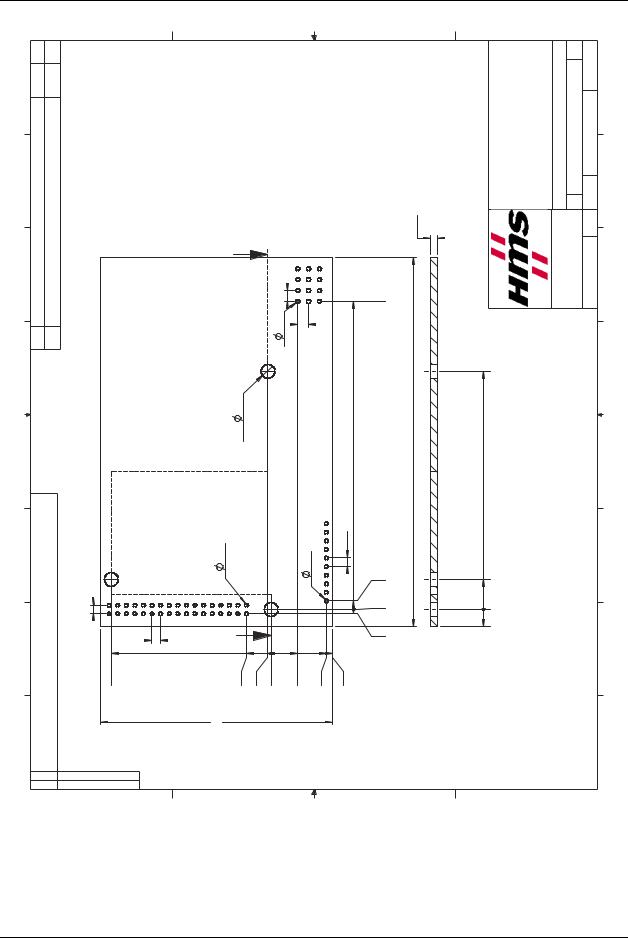
Figure 10: AnyBus-S Modbus Plus Straight Top view
34 |
HMS INDUSTRIAL NETWORKS AB |
FIELDBUS APPENDIX - ANYBUS-S MODBUS PLUS DOC. NO ABS-MBP-1.31 2002-08-09
F |
E |
D |
C |
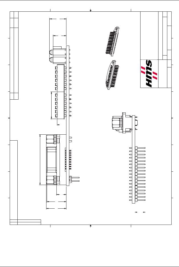
4 3 8,1 10,2
5
alternatives |
Top side |
Application connector |
Bottom side |
|
|
3 |
HMS Industrial Networks AB |
Pilefeltsgatan 93-95 S-302 50 Halmstad Tel: +46 (0)35 - 17 29 00 Fax: +46 (0)35 - 17 29 09 |
4 |
|
UNLESS OTHERWISE SPECIFIED DIMENSIONS ARE IN MILLIMETERS. TOLERANCE: +/- 0,1 |
5 |
6
7
8
9
:
THE INFORMATION CONTAINED IN THIS DRAWING IS THE SOLE PROPERTY OF HMS INDUSTRIAL NETWORKS AB. ANY REPRODUCTION IN PART OR WHOLE WITHOUT THE WRITTEN PERMISSION OF HMS INDUSTRIAL NETWORKS AB IS PROHIBITED.
16,7
 6,7 5,5
30,9
6,0 |
11,9 |
12,2 |
6
7
8
9
|
12,2 mm |
|
: |
|
|
||
|
|
|
|
6,4 - |
|
|
|
F |
E |
D |
C |
Figure 11: AnyBus-S Modbus Plus Straight Front and Side view
HMS INDUSTRIAL NETWORKS AB |
35 |