

AnyBus IO modules design guide.rev1.22
.pdfDesign Guide
Revision 1.22
2000-03-16
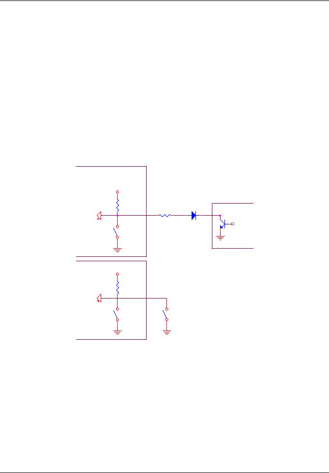
Optocoupler IN:
This connection is isolated and recommended by HMS for the translation from 24V to 5V on the input of the ANYBUS module.
|
Vcc |
In +24V |
|
|
U1 |
|
TLP181 |
|
In_AB |
|
ANYBUS |
R1 |
R2 |
3k9 |
4k7 |
Gnd_24V
Optocoupler OUT:
R 1 |
|
|
O u t _ A B |
|
|
1 k 5 |
U 1 |
|
T L P 1 8 1 |
||
ANYBUS |
||
|
||
C 1 |
|
|
1 0 n |
|
|
|
|
|
|
V c c _ 2 4 V |
|
|
|
|
|||
R 2 |
|
|
Q 1 |
|
|
|
|
|||||
|
|
|
|
|
|
|||||||
|
|
|
|
|
|
|||||||
|
|
|
|
|
|
|
|
|
|
|
||
3 0 k |
|
|
P N P |
|
|
|
Out |
|||||
|
|
|
|
|
|
|
||||||
Transient |
|
2 |
D 1 |
|
|
|
|
|||||
|
|
|
|
|
|
|
||||||
|
|
|
|
|
|
|
||||||
protection |
|
|
|
1 N 4 0 0 4 |
|
|
C 2 |
|||||
|
|
|
|
|
||||||||
|
|
|
|
|
||||||||
Diode |
|
|
|
|
|
|
1 0 n |
|||||
|
|
|
|
|
|
1 |
|
|
|
|
|
|
|
|
|
|
|
|
|
|
|
|
|
||
G n d _ 2 4 V |
G n d _ 2 4 V |
G n d _ 2 4 V |
This connection is isolated and recommended by HMS for the translation from 5V to 24V on the output of the ANYBUS module.
2.3 Power and I/O Connectors
For the power supply and the I/O pin interface the standard ANYBUS connector is a male strip connector. These connectors can be mounted on the top or bottom side of the ANYBUS module. This connectors are available in three different standard length (6.00, 8.13, 10.16mm). Headers for this connectors can easily be ordered from many companies. The ANYBUS modules can be ordered (customer specific) with other connectors. Please ask HMS for more information.
• Available in three standard lengths
• Also available as 90º connector
Figure 5: Male strip connector straight
2.4 Fieldbus Interface
The fieldbus electronics always fulfil the standard of the implemented fieldbus. The ANYBUS concept only specifies the connectors used for the fieldbus interface.
HMS FIELDBUS SYSTEMS AB |
Page 11 (11) |

Design Guide
Revision 1.22
2000-03-16
2.4.1 Fieldbus Connectors
The following connectors are always supported by the ANYBUS modules.
•9-pin D-SUB, straight and angled versions available
•Screw terminal, straight and angled versions available
•Crimp terminal, straight and angled versions available
These connectors are included in the design even if the fieldbus standard has not approved these connectors. Additional connectors can be included. The standard configurations of HMS samples are a 90 D-SUB or screw terminal.
HMS FIELDBUS SYSTEMS AB |
Page 12 (12) |

Design Guide
Revision 1.22
2000-03-16
3 Electrical Specification
This chapter describes the electrical characteristics for the ANYBUS I/O modules. Minimal, typical and maximum currents and voltages specified for each pin of the I/O modules. Other values than specified will cause a breakdown on the fieldbus or destroy the module.
3.1 Power Supply Connector
All voltages measured with respect to device GND pin unless otherwise noted.
Symbol |
Description |
Min. |
Typ. |
Max. |
Unit. |
VCC |
Supply voltage, electronics |
4.75 |
5.00 |
5.25 |
V |
IIN |
Input current |
|
120 |
200 |
mA |
3.1.2 BUS Electronics Electrical Characteristics (pin 1, GNDBUS pin 2)
Symbol |
Description |
Min. |
Typ. |
Max. |
Unit. |
VCC |
Isolated power supply to bus |
4.75 |
5.00 |
5.25 |
V |
|
electronics. |
|
|
|
|
IIN |
Input current |
|
120 |
200 |
mA |
3.1.3 LED Outputs Electrical Characteristics (pin 7-10)
Symbol |
Description |
Min. |
Typ. |
Max. |
Unit |
UCESAT |
Open collector output for indication LED’s |
|
0.2 |
|
V |
IMAX |
Maximum sink current |
|
|
100 |
mA |
3.1.4 Configuration Inputs Electrical Characteristics (pin 11-19)
Symbol |
Description |
Min. |
Typ. |
Max. |
Unit. |
VIH |
High level input voltage |
4.2 |
|
|
V |
VIL |
Low level input voltage |
|
|
0.9 |
V |
IIN |
Input current |
|
|
20 |
mA |
3.1.5 Control Signals Electrical Characteristics (pin 20)
Symbol |
Description |
Min. |
Typ. |
Max. |
Unit. |
VIH |
High level input voltage |
2 |
|
Vcc + 0.5 |
V |
VIL |
Low level input voltage |
0 |
|
0.8 |
V |
VRESET |
Reset active voltage |
|
|
|
V |
tw |
Reset pulse duration, minimum effective |
500 |
|
|
ns |
HMS FIELDBUS SYSTEMS AB |
Page 13 (13) |

Design Guide
Revision 1.22
2000-03-16
3.2 Output Connector
3.2.1 Digital Output Signals Electrical Characteristics (pin 1-16, alt 1-32)
Symbol |
Description |
Min. |
Typ. |
Max. |
Unit. |
VOH |
High level output voltage |
VCC-0.8 |
|
|
V |
VOL |
Low level output voltage |
|
|
0.4 |
V |
IOMAX |
Maximum output current |
|
|
4 |
mA |
3.3 Input Connector
3.3.1 Digital Input Signals Electrical Characteristics (pin 1-16, alt 1-32)
Symbol |
Description |
Min. |
Typ. |
Max. |
Unit. |
VIH |
High level input voltage |
4.0 |
|
|
V |
VIL |
Low level input voltage |
|
|
1.0 |
V |
IIN |
Maximum input current |
|
|
10 |
A |
HMS FIELDBUS SYSTEMS AB |
Page 14 (14) |
Design Guide
Revision 1.22
2000-03-16
4 The ANYBUS I/O Modules
The ANYBUS I/O module appears to the application as a group of logic I/O signals. Its performance is depending on the fieldbus implemented. The functions of the module are specified in this chapter for different modules and fieldbus status.
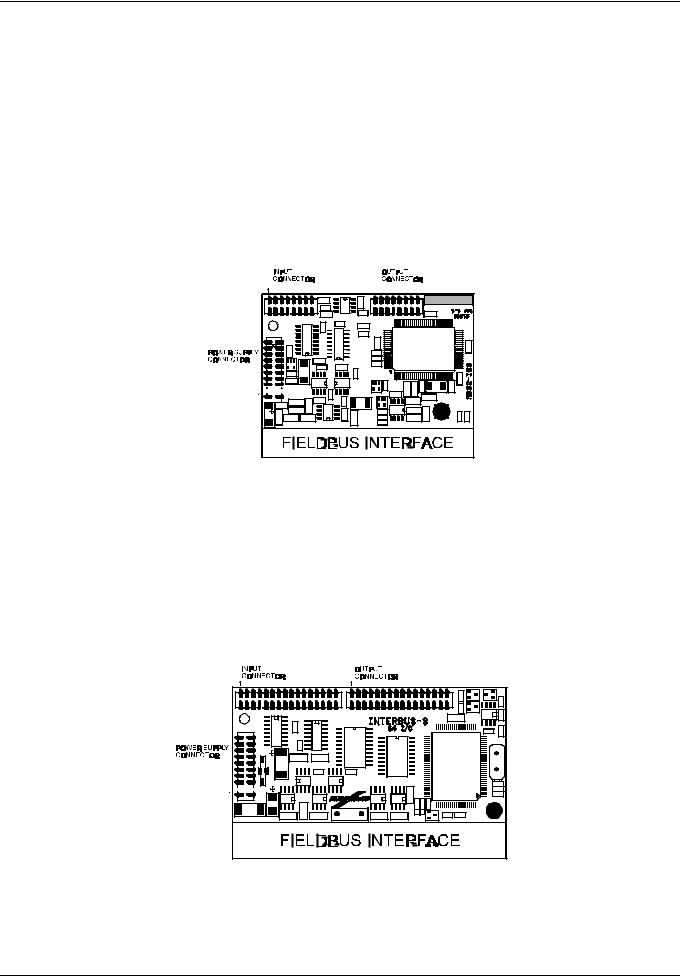
4.1 Module Description
The ANYBUS 32 I/O has a small mechanical design (54x 70mm). It has all necessary fieldbus dependent parts integrated and it has a wide range of bus and product interface connections. It is also pin compatible to the 64 I/O module. For connection to the carrier board the module has three standard connectors; input, output and power supply connectors. For the input and output connectors each pin is a specified input or output.
Figure 4.1: ANYBUS 32 I/O for InterBus-S
The ANYBUS 64 I/O also has a small mechanical design (54x86mm). As the 32 I/O module, it includes all necessary fieldbus dependent parts and it has a wide range of Bus and product interface connections. For connection to the mother board the module has three standard connectors; input, output and power supply connectors. For the input and output connectors each pin is a specified input or output. For specification of the power supply connector see Appendix for each fieldbus. Considering these facts the ANYBUS I/O modules are easy to use in any application.
Figure 4.2: ANYBUS 64 I/O for InterBus
HMS FIELDBUS SYSTEMS AB |
Page 15 (15) |
Design Guide
Revision 1.22
2000-03-16
4.2 Functional Description
RESET and power-up
During power up and reset the ANYBUS module will clear all outputs and reset the module. After each reset a hardware check are made. After the reset the module will initiate it self and wait for a start command from the fieldbus master.
Initialisations
For some fieldbuses the ANYBUS module has switches for configuration standard mounted. If the configuration switches are mounted, the module can not be configured externally via the power supply contact. To be able to do this the address configure switches have to be removed. If the module always will be configured externally it is possible to order a module without switches. How exactly the ANYBUS module is initiated and when it runs normally, is dependent on which fieldbus the ANYBUS module supports (see Appendix for each fieldbus). How to design an external configure input, see figure below.
AnyBus
alternative 1
V c c
R 1 |
|
|
10k |
R 2 |
D 1 |
|
Q 1
1 2
N P N
3 0 0 |
1n4148 |
S 1
S W S P S T
alternative 2
V c c
R 1 1 0 k
S 1 |
S 1 |
S W S P S T |
S W S P S T |
Figure 4.3: External configuration input
4.3 Operation
The ANYBUS module has indication LEDs for the status of the fieldbus and protocol. These LEDs will indicate if everything is working properly or not. For exact information on LED indicators, see Appendix for each fieldbus.
4.4 Fieldbus Error
If a fieldbus error occurs, all ANYBUS modules will handle the error due to each fieldbus specific standard. See Appendix for the specified fieldbus.
HMS FIELDBUS SYSTEMS AB |
Page 16 (16) |
Design Guide
Revision 1.22
2000-03-16
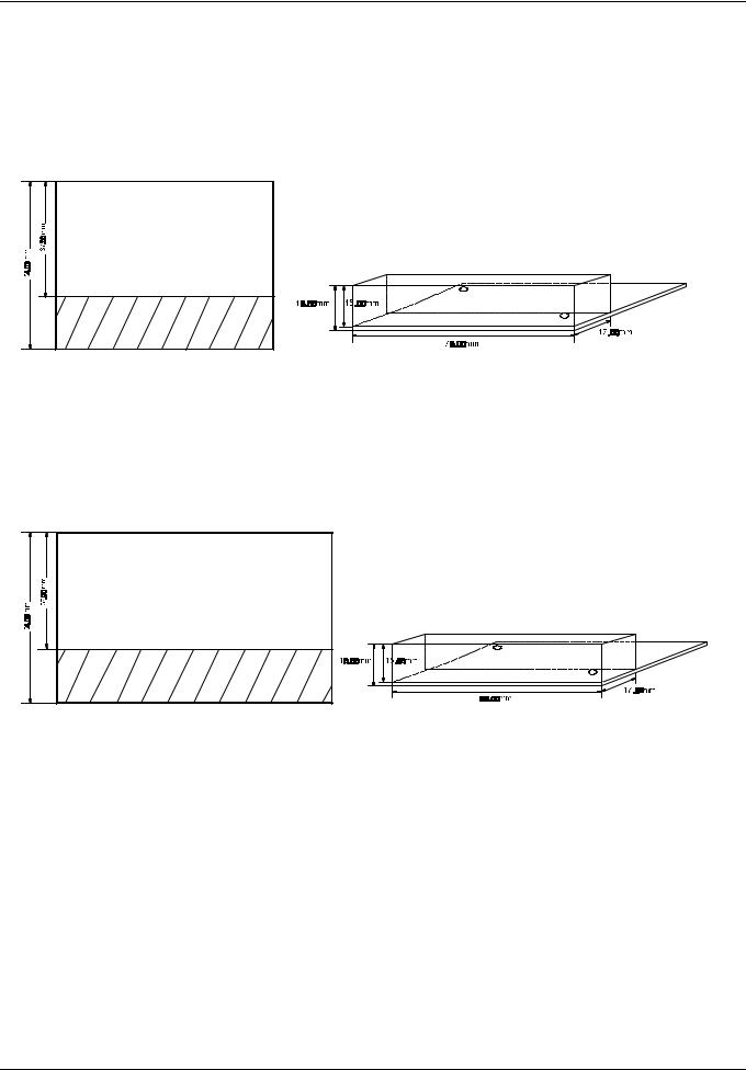
5 Mechanical Design Specification
All ANYBUS 32 and 64 I/O modules are mechanically compatible. This, and the fact that the two I/O modules (32 and 64) are pin compatible means that the ANYBUS modules are interchangeable regardless of which fieldbus system that is being supported.
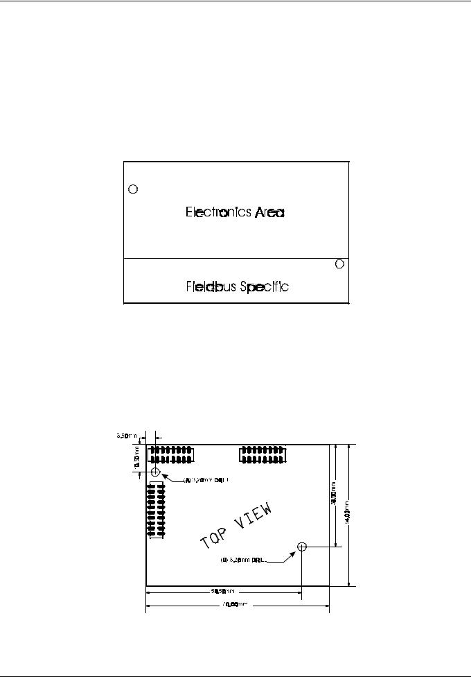
According to the conditions above the mechanical design of the ANYBUS 32 (64) I/O module can be divided into three main areas on the PCB:
2.Fieldbus interface specific area
3.Product interface and electronics area
Figure 5.1: ANYBUS specific areas
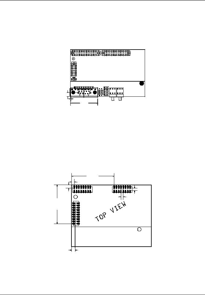
5.1 Mechanical Layout of the PCB
5.1.1 32 I/O Module
The PCB of an ANYBUS 32 I/O module has the following mechanical measurements:
Figure 5.2: ANYBUS 32 I/O top view
HMS FIELDBUS SYSTEMS AB Page 17 (17)
Design Guide
Revision 1.22
2000-03-16
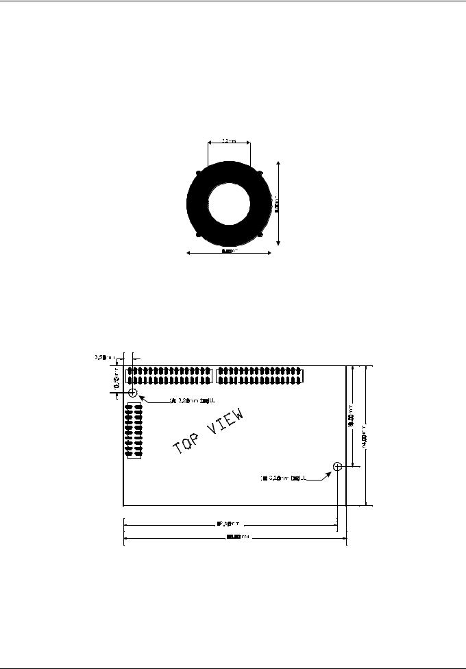
The mounting holes on the PCB board have the following functions for both 32 and 64 I/O:
A:Mounting hole for use of non conducting screw or similar device
B:Mounting hole for use of conducting screw or similar (connected to PE).
In the design guide for the 32 I/O and the 64 I/O module it is specified that hole B always should be connected to PE (Protective Earth). Some bus systems requires a PE connection for proper shield installation etc. This hole is always a metal coated hole (VIA) according figure below.
Figure 5.3: PE Connection
5.1.2 64 I/O Module
The PCB of a ANYBUS 64 I/O module has the following mechanical measurements
Picture 5.4: ANYBUS 64 I/O top view
HMS FIELDBUS SYSTEMS AB |
Page 18 (18) |
Design Guide
Revision 1.22
2000-03-16
5.2 Fieldbus Interface Specific Area
Since connectors and components for the different AnyBus modules varies from the different fieldbus systems, a fieldbus specific area is included.
5.2.1 32 I/O Module
The Fieldbus specific area has the following mechanical measurements for the 32 I/O module.
Figure 5.5: ANYBUS 32 I/O Fieldbus specific area
5.2.2 64 I/O Module
The fieldbus specific area has the following mechanical measurements for the 64 I/O module.
Figure 5.6: ANYBUS 64 I/O Fieldbus specific area
HMS FIELDBUS SYSTEMS AB |
Page 19 (19) |
Design Guide
Revision 1.22
2000-03-16
5.2.3 Component Placement
The fieldbus dependent part is composed of different components, and the components are placed in a specified order. This order depends on which fieldbus the ANYBUS module supports. The only connector that is placed at the same position on all ANYBUS modules, is the first fieldbus connector. If the fieldbus requires more than one connector, the second is placed at a position that is most suitable for the design. See Appendix for detailed order of component placement, fieldbus specific.
mm |
2 |
3 |
4 |
5 |
6 |
7 |
8 |
9 |
1 |
||||||||
4.5 0 |
|
|
|
|
|
|
|
|
|
|
|
|
|
|
1 |
|
|
|
|
|
9 |
|
|
|
|
|
0.45m m |
|
|
|
|
|
|
|
|
|
|
|
3 1.54m m |
|
|
|
||
Figure 5.7: Fieldbus Interface ANYBUS 64 for Profibus-DP
Please note that the form factor is dependent on what configuration switches and connectors that are being used.
5.3 Product Interface and Electronics Area
5.3.1 32 I/O Module
The remaining area of the ANYBUS 32 I/O module is designed according to the following specification.
|
|
3 7 .5 0 m m |
|
|
|
2 .5 0 m m |
|
|
|
|
|
1 |
1 |
|
|
m |
16 |
|
16 |
|
m |
|
2 .0 0 m m |
m |
|
3 .0 0 |
|
2 .0 0 m |
|
m m |
2 0 |
|
||
3 4 .0 0 |
|
|
|
|
|
|
1 |
|
|
|
3 .0 0 m m |
|
|
|
Figure 5.8: ANYBUS 32 I/O top view
The connectors to the application are male strip connector type and are placed according to Picture 5.3.1. The maximum height of the components in this area (application connectors not included) is 5 mm. Maximum height of the components in the area on the bottom side is 4 mm.
HMS FIELDBUS SYSTEMS AB |
Page 20 (20) |