

09.Datapaths
.pdfChapter 9 − Datapaths Page 11 of 24
ARCHITECTURE Behavioral OF mux2 IS
BEGIN
PROCESS(S, D1, D0)
BEGIN
IF(S = '0' )THEN
Y <= D0;
ELSE
Y <= D1;
END IF;
END PROCESS;
END Behavioral;
-------------------------------------------------------------------------
-- Register File LIBRARY ieee;
USE ieee.std_logic_1164.all;
USE ieee.std_logic_unsigned.all; --USE ieee.std_logic_arith.all;
ENTITY regfile IS PORT ( |
|
|
clk: IN std_logic; |
--clock |
|
WE: IN std_logic; |
--write enable |
|
WA: IN std_logic_vector(1 DOWNTO 0); |
--write address |
|
input: IN std_logic_vector(7 DOWNTO 0); |
--input |
|
RAE: IN std_logic; |
--read enable ports A & B |
|
RAA: IN std_logic_vector(1 DOWNTO 0); |
--read address port A & B |
|
RBE: IN std_logic; |
--read enable ports A & B |
|
RBA: IN std_logic_vector(1 DOWNTO 0); |
--read address port A & B |
|
Aout, Bout: OUT std_logic_vector(7 DOWNTO 0)); |
--output port A & B |
|
END regfile; |
|
|
ARCHITECTURE Behavioral OF regfile IS |
|
|
SUBTYPE reg IS std_logic_vector(7 DOWNTO 0); |
|
|
TYPE regArray IS array(0 TO 3) OF reg; |
|
|
SIGNAL RF: regArray; |
--register file contents |
|
BEGIN |
|
|
WritePort: PROCESS (clk) |
|
|
BEGIN |
|
|
IF (clk'EVENT AND clk = '1') THEN |
|
|
IF (WE = '1') THEN |
|
|
RF(CONV_INTEGER(WA)) <= input; |
|
|
END IF; |
|
|
END IF; |
|
|
END PROCESS; |
|
|
ReadPortA: PROCESS (RAE, RAA) BEGIN
IF (RAE = '1') then
Aout <= RF(CONV_INTEGER(RAA)); -- convert bit VECTOR to integer ELSE
Aout <= (others => 'Z'); END IF;
END PROCESS;
ReadPortB: PROCESS (RBE, RBA)
BEGIN
IF (RBE = '1') then
Microprocessor Design – Principles and Practices with VHDL |
Last updated 7/16/2003 12:32 PM |

Chapter 9 − Datapaths |
Page 12 of 24 |
|
|
|
|
|
Bout <= RF(CONV_INTEGER(RBA)); -- convert bit VECTOR to integer |
|
|
ELSE |
|
|
Bout <= (others => 'Z'); |
|
|
END IF; |
|
|
END PROCESS; |
|
|
END Behavioral; |
|
-------------------------------------------------------------------------
--ALU LIBRARY ieee;
USE ieee.std_logic_1164.all;
--need the following to perform arithmetics on std_logic_vectors USE ieee.std_logic_unsigned.all;
ENTITY alu IS |
PORT ( |
|
|
ALUSel: IN |
std_logic_vector(2 DOWNTO 0); |
-- select for operations |
|
A, B: IN std_logic_vector(7 DOWNTO 0); |
-- input operands |
||
F: OUT std_logic_vector(7 DOWNTO 0)); |
-- output |
||
END alu; |
|
|
|
ARCHITECTURE Behavior OF alu IS |
|
||
BEGIN |
|
|
|
PROCESS(ALUSel, A, B) |
|
|
|
BEGIN |
|
|
|
CASE ALUSel IS |
|
|
|
WHEN |
"000" => |
-- pass A through |
|
F |
<= A; |
|
|
WHEN |
"001" => |
-- AND |
|
F |
<= A AND B; |
|
|
WHEN |
"010" => |
-- OR |
|
F |
<= A OR B; |
|
|
WHEN |
"011" => |
-- NOT |
|
F |
<= NOT A; |
|
|
WHEN |
"100" => |
-- add |
|
F |
<= A + B; |
|
|
WHEN |
"101" => |
-- subtract |
|
F |
<= A - B; |
|
|
WHEN |
"110" => |
-- increment |
|
F |
<= A + 1; |
|
|
WHEN |
others => |
-- decrement |
|
F |
<= A - 1; |
|
|
END CASE; |
|
|
|
END PROCESS; |
|
|
|
END Behavior; |
|
|
|
-------------------------------------------------------------------------
-- Shifter LIBRARY ieee;
USE ieee.std_logic_1164.all;
ENTITY shifter IS PORT ( |
|
|
SHSel: IN |
std_logic_vector(1 DOWNTO 0); |
-- select for operations |
input: IN |
std_logic_vector(7 DOWNTO 0); |
-- input operands |
output: OUT std_logic_vector(7 DOWNTO 0)); |
-- output |
|
END shifter; |
|
|
ARCHITECTURE |
Behavior OF shifter IS |
|
Microprocessor Design – Principles and Practices with VHDL |
Last updated 7/16/2003 12:32 PM |

Chapter 9 − Datapaths |
Page 13 of 24 |
|
|
|
|
|
BEGIN |
|
|
PROCESS(SHSel, input) |
|
|
BEGIN |
|
|
CASE SHSel IS |
|
|
WHEN "00" => |
-- pass through |
|
output <= input; |
|
|
WHEN "01" => |
-- shift right |
|
output <= input(6 DOWNTO 0) & '0'; |
|
|
WHEN "10" => |
-- shift left |
|
output <= '0' & input(7 DOWNTO 1); |
|
|
WHEN OTHERS => |
-- rotate right |
|
output <= input(0) & input(7 DOWNTO 1); |
|
|
END CASE; |
|
|
END PROCESS; |
|
|
END Behavior; |
|
|
------------------------------------------------------------------------- |
|
|
-- Tri-state buffer |
|
|
LIBRARY ieee; |
|
|
USE ieee.std_logic_1164.all; |
|
|
ENTITY TriStateBuffer IS PORT ( |
|
|
E: IN std_logic; |
|
|
D: IN std_logic_vector(7 DOWNTO 0); |
|
|
Y: OUT std_logic_vector(7 DOWNTO 0)); |
|
|
END TriStateBuffer; |
|
|
ARCHITECTURE Behavioral OF TriStateBuffer IS |
|
|
BEGIN |
|
|
PROCESS (E, D) -- get error message if no d |
|
|
BEGIN |
|
|
IF (E = '1') THEN |
|
|
Y <= D; |
|
|
ELSE |
|
|
Y <= (OTHERS => 'Z'); |
-- to get 8 Z values |
|
END IF; |
|
|
END PROCESS; |
|
|
END Behavioral; |
|
Figure 12. Components for the datapath of Figure 10.
LIBRARY ieee;
USE ieee.std_logic_1164.all;
ENTITY datapath IS PORT ( clock: IN std_logic;
input: IN std_logic_vector( 7 DOWNTO 0 ); IE, WE: IN std_logic;
WA: IN std_logic_vector (1 DOWNTO 0); RAE: IN std_logic;
RAA: IN std_logic_vector (1 DOWNTO 0); RBE: IN std_logic;
RBA: IN std_logic_vector (1 DOWNTO 0); aluSel: IN std_logic_vector(2 DOWNTO 0); shSel: IN std_logic_vector (1 DOWNTO 0); OE: IN std_logic;
Microprocessor Design – Principles and Practices with VHDL |
Last updated 7/16/2003 12:32 PM |
Chapter 9 − Datapaths |
|
Page 14 of 24 |
|
|
|
|
|
|
output: OUT std_logic_vector(7 DOWNTO 0)); |
|
|
|
END datapath; |
|
|
|
ARCHITECTURE Structural OF datapath IS |
|
|
|
COMPONENT mux2 PORT ( |
|
|
|
S: IN std_logic; |
-- select lines |
|
|
D1, D0: IN std_logic_vector(7 DOWNTO 0); |
-- data bus input |
|
|
Y: OUT std_logic_vector(7 DOWNTO 0)); |
-- data bus output |
|
|
END COMPONENT; |
|
|
|
COMPONENT regfile PORT ( |
|
|
|
clk: IN std_logic; |
--clock |
|
|
WE: IN std_logic; |
--write enable |
|
|
WA: IN std_logic_vector(1 DOWNTO 0); |
--write address |
|
|
input: IN std_logic_vector(7 DOWNTO 0); |
--input |
|
|
RAE: IN std_logic; |
--read enable ports A & B |
|
|
RAA: IN std_logic_vector(1 DOWNTO 0); |
--read address port A & B |
|
|
RBE: IN std_logic; |
--read enable ports A & B |
|
|
RBA: IN std_logic_vector(1 DOWNTO 0); |
--read address port A & B |
|
|
Aout, Bout: OUT std_logic_vector(7 DOWNTO 0)); |
--output port A & B |
|
|
END COMPONENT; |
|
|
|
COMPONENT alu PORT ( |
|
|
|
ALUSel: IN std_logic_vector(2 DOWNTO 0); |
-- select for operations |
|
|
A, B: IN std_logic_vector(7 DOWNTO 0); |
-- input operands |
|
|
F: OUT std_logic_vector(7 DOWNTO 0)); |
-- output |
|
|
END COMPONENT; |
|
|
|
COMPONENT shifter PORT ( |
|
|
|
SHSel: IN std_logic_vector(1 DOWNTO 0); |
-- select for operations |
|
|
input: IN std_logic_vector(7 DOWNTO 0); |
-- input operands |
|
|
output: OUT std_logic_vector(7 DOWNTO 0)); |
-- output |
|
|
END COMPONENT; |
|
|
|
COMPONENT tristatebuffer PORT ( |
|
|
|
E: IN std_logic; |
|
|
|
D: IN std_logic_vector(7 downto 0); |
|
|
|
Y: OUT std_logic_vector(7 downto 0)); |
|
|
|
END COMPONENT; |
|
|
|
SIGNAL muxout, rfAout, rfBout: std_logic_vector( 7 DOWNTO 0 ); |
||
|
SIGNAL aluout, shiftout, tristateout: std_logic_vector( 7 DOWNTO 0 ); |
||
|
BEGIN |
|
|
|
-- doing structural modeling here |
|
|
|
U0: mux2 PORT MAP( IE, input, shiftout, muxout ); |
|
|
|
U1: regfile PORT MAP(clock,WE,WA,muxout,RAE,RAA,RBE,RBA,rfAout,rfBout ); |
||
|
U2: alu PORT MAP( ALUsel, rfAout, rfBout, aluout ); |
||
|
U3: shifter PORT MAP(SHSel,aluout,shiftout); |
|
|
|
U4: tristatebuffer PORT MAP(OE, shiftout, tristateout); |
||
|
output <= tristateout; |
|
|
|
END Structural; |
|
|
|
|
|
|
Figure 13. Datapath of Figure 10 constructed at the structural level. |
|
|
|
Microprocessor Design – Principles and Practices with VHDL |
Last updated 7/16/2003 12:32 PM |
Chapter 9 − Datapaths |
Page 15 of 24 |
9.6Dedicated Datapath
When designing a dedicated microprocessor to perform a certain algorithm, there are times when we may not want to use a general datapath and build a control unit to control it. The disadvantage of using a general datapath is that there will usually be some parts in the datapath that are not needed in solving the problem. For example, the shifter in the general datapath of Figure 10(a) was not needed in the summation algorithm of Figure 9(a). These extra parts are not only wasted, but they increase the size and power consumption of the circuit. Furthermore, since a custom datapath is smaller than a general datapath, they will also require fewer control signals. Because fewer control signals need to be generated, the resulting control unit will also be simpler to design and smaller. Hence, we benefit not only from a smaller datapath but also a smaller control unit, and so resulting in a much smaller microprocessor. Thus, instead of using a general datapath, we may want to design a dedicated or custom datapath just for solving the given algorithm.
Keep in mind that we are trying to build a circuit for executing a given algorithm, and that the datapath is responsible for performing all the data manipulations specified by the algorithm. Therefore, the datapath must be able to perform all the data manipulation statements and generate all the conditional status signals for the algorithm. In a dedicated datapath or register-transfer level design, we are concerned with how data moves from a register to a (same or different) register via some functional units where the data is modified. When constructing a datapath for performing a specific algorithm, we need to decide on the following issues:
•How many and what kind of registers are needed?
•What kind of functional units and how many are needed?
•Can a certain functional unit be shared between two or more operations?
•How are the registers and functional units connected together so that all the data movements specified by the algorithm can be realized?
9.6.1 Selecting Registers
In most situations, one register is needed for each variable used by the algorithm. However, if the lifetime of two variables does not overlap then they can share using the same register. The lifetime of a variable is the time between when the variable is first used to when it is last used.
If two or more variables share the same register, then the data transfer connections leading to the register and out from the register are usually made more complex since the register now has more than one source and destination. Having multiple destinations is not too big of a concern in terms of circuit size. However, having multiple sources will require extra circuitry to select which one of the several sources is to be transferred to the register.
After deciding how many registers are needed, we still need to determine whether to use a single register file or separate registers or a combination of both for storing these variables in. Furthermore, registers with built-in special functions such as the counters and shift registers discussed in Sections 7.5 and 7.6 can also be used. Decisions for selecting the type of registers to use will affect how the data transfer connections between the registers and functional units are connected.
9.6.2 Selecting Functional Units
It is fairly straight forward to decide what kind of functional units are required. For example, if the algorithm requires the addition of two numbers, then the datapath must include an adder. However, we still need to decide whether to use a dedicated adder, an adder/subtractor combination, or an ALU (which has the addition operation implemented). Of course, these questions can be answered by knowing what other data operations are needed by the algorithm. If the algorithm has only an addition and a subtraction, then you may want to use the adder/subtractor combination unit. On the other hand, if the algorithm requires several addition operations, do we use just one adder or several adders?
Using one adder may decrease the datapath size in terms of number of functional units, but it may also increase the datapath size because more complex data transfer paths are needed. For example, if the algorithm contains the following two addition operations:
Microprocessor Design – Principles and Practices with VHDL |
Last updated 7/16/2003 12:32 PM |
Chapter 9 − Datapaths |
Page 16 of 24 |
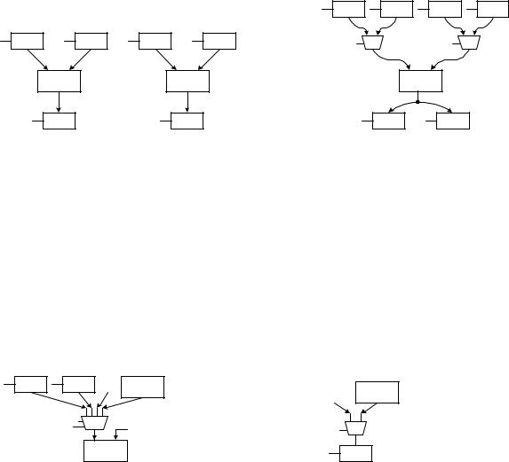
a = b + c d = e + f
Using two separate adders will result in the datapath shown in Figure 14(a), whereas, using one adder will require the use of two extra 2-to-1 multiplexers to select which register will supply the input to the adder operands as shown in Figure 14(b).
|
|
|
|
b |
|
e |
c |
f |
b |
c |
e |
f |
s |
y |
|
s |
y |
|
|
|
|
1 |
0 |
|
1 |
0 |
|
+ |
|
+ |
|
|
|
+ |
|
|
a |
|
d |
|
|
a |
d |
|
|
|
(a) |
|
|
|
|
(b) |
|
Figure 14. Datapaths for realizing two addition operations: (a) using two separate adders; (b) using one adder.
9.6.3 Data Transfer Methods
There are several methods in which the registers and functional units can be connected together so that the correct data transfers between the units are made.
Multiple Sources
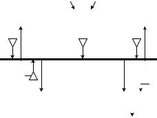
If the input to a unit has more than one source, then a multiplexer can be used to select which one of the multiple sources to use. The sources can be from registers, constant values, or outputs from other functional units. Figure 15 shows two such examples. In Figure 15(a), the left operand of the adder has four sources: two from registers, one from the constant 1, and one from the output of an ALU. In Figure 15(b), register a has two sources: one from the constant 1, and one from the output of an adder.
a b '1' ALU
3 2 1 0 s1
s0 y
+
(a)
Figure 15. Examples of multiple sources using multiplexers.
Multiple Destinations
'1' +
1 |
0 |
s |
y |
a
(b)
A source having multiple destinations does not require any extra circuitry. The one source can be connected directly to the different destinations, and all the destinations where the data is not needed would simply ignore the data source. For example, in Figure 14(b), the output of the adder has two destinations: register a and register d. If the output of the current addition is for register a, then the Load line for register a is asserted while the Load line for register d is not, and if the output is for register d, then the Load line for register d is asserted while the Load line for register a is not. In either case, only the correct register will take the data while the other units will simply ignore the data.
Microprocessor Design – Principles and Practices with VHDL |
Last updated 7/16/2003 12:32 PM |
Chapter 9 − Datapaths |
Page 17 of 24 |
This also works if one of the destinations is a combinational functional unit. In this case, the functional unit will take the source data and manipulates it. However, the output of the functional unit will not be used, that is not stored in any register, so functionally it doesn’t matter that the functional unit worked on the source because the result is not used by any unit. However, it does require power for the functional unit to manipulate the data, so if we want to reduce power consumption, we would want the functional unit to not manipulate the data.
Tri-state Bus
Another scheme where multiple sources and destinations can be connected on the same data bus is through the use of tri-state buffers. The point to note here is that when multiple sources are connected to the same bus, only one source can output at any one time. If two or more sources output to the same bus at the same time, then there will be data conflicts. One source can output a 0 while another source outputs a 1. By using tri-state buffers connected between the sources and the common bus, only one tri-state buffer is enabled while the rest of them are all disabled. Tri-state buffers that are disabled output high impedance Z values so no data conflicts can occur.
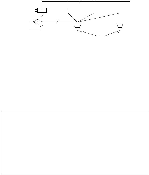
Figure 16 shows a tri-state bus with five units (three registers, an ALU, and an adder) connected to it. An advantage of using a tri-state bus is that the bus is bi-directional so that data can travel in both directions on the bus. Connections for data going from a component to the bus need to be tri-stated while connections for data going from the bus to a component need not be. Notice also that data input and output of a register can both be connected to the same tri-state bus, whereas, the input and output of a functional unit (such as the adder or ALU) cannot be both connected to the same tri-state bus.
|
|
|
|
|
ALU |
|
|
|
|
|
|||
|
|
|
a |
|
|
|
|
|
b |
||||
|
|
|
|
|
|
||||||||
|
|
|
|
|
|
|
|
|
|
|
|
|
|
|
|
|
|
|
|
|
|
|
|
|
|
|
|
common data bus
|
|
|
|
|
|
|
|
|
|
|
|
|
|
|
|
|
|
|
|
|
|
c |
|
+ |
|
||
|
|
|||||
|
|
|
|
|
|
|
|
|
|
|
|
|
|
Figure 16. Multiple sources using tri-state buffers to share a common data bus.
9.7Using a Dedicated Datapath
Using a dedicated datapath is exactly the same as using a general datapath. Once we have constructed a dedicated datapath, we will then write the control words for controlling the datapath.
9.8Examples: Designing Dedicated Datapaths
We will now illustrate the design of dedicated datapaths with several examples.
Example 9.4
For example, to construct a dedicated datapath for the counting problem of Example 8.1, we can start with the simple general datapath of Figure 1 and see what we can eliminate. Well, we can replace the ALU with a simple adder since all we need is to increment. We can also remove the multiplexer and connect the constant ‘1’ directly to one of the operands of the adder, since no external input is required. The resulting datapath is shown in Figure 17(a).
Another approach in designing a custom datapath is to start from scratch and decide what components are needed. We want to pick the best match components and as few as possible to solve the problem. For the counting problem, since all we wanted to do is count from 1 to 10, we can just use a 4-bit up counter as shown in Figure 17(b). ♦
Microprocessor Design – Principles and Practices with VHDL |
Last updated 7/16/2003 12:32 PM |

Chapter 9 − Datapaths |
Page 18 of 24 |
Example 8.5 shows a slightly more complicated dedicated datapath construction.
'1'
|
|
|
|
|
|
|
|
|
|
|
|
|
|
|
|
|
|
|
|
|
|
|
|
|
|
|
Adder |
|
|
|
|
|
|||
|
|
|
|
|
|
|
|
Count |
|
|
|
|
|
|
|
|
|
|
|
|
|
|
|
|
|
|
|
|
|
|
|
|
|
|
|
2 |
|
Load |
|
|
|
4-bit binary up counter |
|||||
1 |
|
Clear Register |
|
Clear |
|
||||||
|
|
||||||||||
Clk |
|
|
|
|
|
||||||
|
|
|
|
|
|
|
Clk |
|
Q |
||
|
|
|
|
|
|
|
|
||||
|
|
|
|
|
|
|
|
|
|
||
0 |
OE |
|
|
|
|
OE |
|
4 |
|||
|
|
|
|
|
|||||||
|
|
|
|
|
|
|
|||||
|
|
|
|
||||||||
|
|
|
|
|
|
|
|
|
|
||
|
|
|
|
|
|
|
|
|
|
||
|
|
|
|
|
|
|
|
|
|
|
|
|
|
|
Output |
|
|
Output |
|||||
|
|
|
(a) |
|
|
(b) |
|||||
Figure 17. Dedicated datapath for solving the counting problem of Example 9.1: (a) modifications of the simple datapath; (b) custom design from scratch.
Example 9.5
In this example, we want to construct a dedicated datapath for solving the following algorithm:
w = 0 x = 0 y = 0
input z
while (z ≠ 0) { w = w – 2
if (z is an odd number) x = x + 2
else
y = y + 1 z = z – 1
}
We first note that we need to have four registers with load and clear for storing the four variables used in the algorithm. In addition, we need an adder/subtractor combination unit to be able to add and subtract either of the two constants 1 and 2. The resulting dedicated datapath is shown in Figure 18. We assume that the data path widths are all eight bits, while the control and select lines are all one bit.
For initializing the three variables w, x, and y to zero, we can simply assert the clear line on the respective registers. The statement “input z” is done by asserting the load line to the register for storing z. For the statement “w = w – 2”, we need to connect the output of the w register to the left operand of the adder/subtractor unit and the constant 2 to the right operand. The output of the adder/subtractor unit is connected back to the input of the w register. Similar connections can be made for the next three data manipulation statements “x = x + 2”, “y = y + 1”, and “z = z – 1”.
Since the left operand of the adder/subtractor unit has four sources (w, x, y, and z), we need to add a 4-to-1 multiplexer to select from one of the four sources. The output of the mux then goes to the left operand of the
Microprocessor Design – Principles and Practices with VHDL |
Last updated 7/16/2003 12:32 PM |
Chapter 9 − Datapaths |
Page 19 of 24 |
adder/subtractor. Similarly, the right orperand of the adder/subtractor has two sources (the constants 1 and 2), we need a 2-to-1 mux to route the correct constant to the adder/subtractor.
The comparator for the while loop condition (z ≠ 0) is a NOR gate with as many inputs as the databus width. The test for (z is an odd number) can simply extract the least significant bit of z since an odd number always has a 1 in
the least significant bit. |
♦ |
|
8 |
|
Load_z |
z |
|
Clear_z |
|
|
|
|
|
|
8 |
(z ≠ |
0) |
LSB |
|
|
|
(z is odd) |
|
|
Load_y |
|
|
|
|
|
|
|
Load_x |
|
|
|
|
|
|
Load_w |
|
|
|
|
|
|
|
|
|||
|
y |
|
|
|
|
x |
|
|
w |
|
||||||||||||||||
Clear_y |
|
|
|
|
|
Clear_x |
|
|
|
Clear_w |
|
|
|
|
||||||||||||
|
|
|
|
|
|
|
|
|
|
|
|
|
|
|
|
|
|
|
|
|||||||
8 |
|
|
|
|
|
|
|
|
|
|
|
|
|
|
|
|
|
|
|
'1' |
'2' |
|
||||
|
|
|
|
|
|
|
|
|
|
|
|
|
|
|
|
|
|
|
|
|
||||||
|
|
|
|
|
|
|
|
|
|
|
|
|
|
|
|
|
|
|
|
|
|
|
|
|
||
|
|
s |
|
3 |
2 |
1 |
0 |
|
|
|
|
|
|
|
s |
1 |
0 |
|
||||||||
|
|
|
|
s0 |
y |
|
|
|
|
|
|
|
|
y |
|
|||||||||||
|
|
s1 |
s1 |
|
|
|
|
|
|
|
|
|
|
|
|
|
|
s |
|
|
|
|
||||
|
|
0 |
|
|
|
|
|
|
|
|
|
|
|
|
|
|
|
|
|
|
|
|
|
|
|
|
|
|
|
|
|
|
|
|
|
|
|
|
|
|
|
|
|
|
|
|
|
|
|
|
|
|
|
|
|
|
|
|
|
|
|
|
|
|
|
|
|
|
|
|
|
|
|
|
|
|
|
|
||
|
|
|
|
|
|
|
8 |
|
|
|
|
|
|
|
|
|
|
8 |
|
|
||||||
|
|
|
|
|
|
|
|
|
|
|
|
|
|
|
|
|
|
|
|
|
|
|
||||
|
|
|
|
|
|
|
|
|
Subtract |
|
|
|
+/− |
|
|
|
|
|
|
|
|
|
|
|||
|
|
|
|
|
|
|
|
|
|
|
|
|
|
|
|
|
|
|
|
|
|
|||||
|
|
|
|
|
|
|
|
|
|
|
|
|
|
|
|
|
|
|
|
|
|
|
|
|
|
|
|
|
|
|
|
|
|
|
|
|
|
|
|
|
|
|
|
|
|
|
|
|
|
|
|
|
|
Figure 18. Dedicated datapath for Example 8.5.
When designing a datapath, all the components in the datapath do not have to be interconnected. The datapath can consist of two or more totally disjoint circuits as shown in Example 8.6.
Example 9.6 – Count Zero-One
In this example, we want to construct a custom datapath for solving the following problem:
Input an 8-bit number. Output a 1 if the number has the same number of 0’s and 1’s, otherwise, output a 0. e.g. the number 10111011 will produce a 0 output, whereas, the number 10100011 will produce a 1 output.
The algorithm for solving the problem is shown in Figure 19. The while loop is executed eight times using the counteight variable for the eight bits in the input number n. For each bit in n, if it is a 1, the variable countbit is incremented, otherwise, it is decremented. At the end of the while loop, if countbit is equal to 0, then there are the same number of 0’s and 1’s in n.
input n
countbit = 0 // for counting the number of zero and one bits counteight = 0 // for looping eight times
while counteight ≠ 8 {
if LSB(n) = 1 // least significant bit of n countbit = countbit + 1
else
countbit = countbit - 1
n = n >> 1 // shift n right one bit counteight = counteight + 1;
}
if countbit = 0 then output 1
else
output 0
Microprocessor Design – Principles and Practices with VHDL |
Last updated 7/16/2003 12:32 PM |
Chapter 9 − Datapaths |
Page 20 of 24 |
assert OutDone
Figure 19. Algorithm for solving the count zero-one problem of Example 8.6.
The functional units and registers required by the custom datapath are as follows:
•A shifter with parallel load register for storing n.
•One 4-bit up counter for counteight.
•One 4-bit up/down counter for countbit.
•A “not equal to 8” comparator for looping eight times.
•An “equal to 0” comparator for testing with countbit.
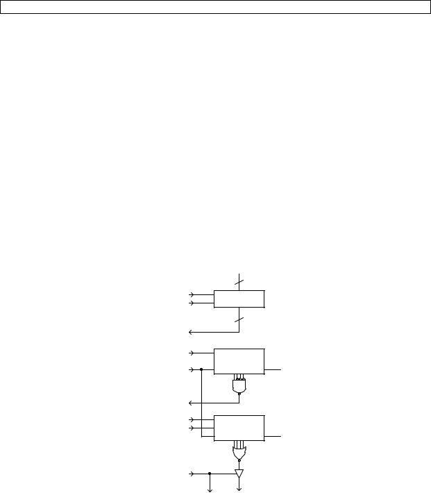
The dedicated datapath for implementing the algorithm is shown in Figure 20. Notice that there are no connections between the shifter and the two counters; they are completely separate circuits. To extract the least significant bit of n and test whether it is equal to a 1 or not, we only have to connect to the least significant bit (LSB) of the shifter and no active component is necessary. To test for counteight ≠ 8, we use a 4-input NAND gate with the least three significant input bits inverted. When counteight is equal to eight, the NAND gate outputs a 0, which serves as the ending loop condition. Since countbit is keeping track of the number of 0’s and 1’s, so if it is a 0 at the end, it means that there are the same number of 0’s and 1’s in n. The NOR gate will output a 1 if countbit is a 0. Whether the output of the NOR gate is actually outputted will depend on whether the tri-state buffer is enabled or not. When the control unit asserts the OutDone line to enable the tri-state buffer, this 1 signal also serves as the Done signal to inform the external user that the computation is completed. In other words, when the Done signal is asserted, the
output value is the result of the computation. |
|
♦ |
|
Input |
|
|
8 |
|
Load |
shifter with |
|
Shift |
load |
|
|
LSB |
|
(LSB = 1) |
|
|
Count_e |
4-bit up |
|
Clear |
counter |
Clock |
counteight |
||
(counteight ≠ 8) |
|
|
Count_b |
4-bit u/d |
|
Down |
counter |
Clock |
|
countbit |
OutDone
Done Output
Figure 20. Dedicated datapath for solving the count zero-one problem of Example 8.6.
Example 9.7
This example designs a dedicated datapath for evaluating the factorial of n. The factorial of n is defined to be the product of 1 × 2 × 3 × … × n. Figure 21 shows the algorithm for solving the factorial of n where n is a user input number.
Microprocessor Design – Principles and Practices with VHDL |
Last updated 7/16/2003 12:32 PM |