

5.Reference
.pdf110 |
CHAPTER 8. TROUBLESHOOTING { THEORY AND PRACTICE |
²Diodes open (rectifying diodes) or shorted (Zener diodes).
²Inductor and transformer windings open or shorted to conductive core. Failures related to overheating (insulation breakdown) are easily detected by smell.
²Resistors open, almost never shorted. Usually this is due to overcurrent heating, although it is less frequently caused by overvoltage transient (arc-over) or physical damage (vibration or impact). Resistors may also change resistance value if overheated!
8.6Likely failures in unproven systems
"All men are liable to error;"
John Locke
Whereas the last section deals with component failures in systems that have been successfully operating for some time, this section concentrates on the problems plaguing brand-new systems. In this case, failure modes are generally not of the aging kind, but are related to mistakes in design and assembly caused by human beings.
8.6.1Wiring problems
In this case, bad connections are usually due to assembly error, such as connection to the wrong point or poor connector fabrication. Shorted failures are also seen, but usually involve misconnections (conductors inadvertently attached to grounding points) or wires pinched under box covers.
Another wiring-related problem seen in new systems is that of electrostatic or electromagnetic interference between di®erent circuits by way of close wiring proximity. This kind of problem is easily created by routing sets of wires too close to each other (especially routing signal cables close to power conductors), and tends to be very di±cult to identify and locate with test equipment.
8.6.2Power supply problems
Blown fuses and tripped circuit breakers are likely sources of trouble, especially if the project in question is an addition to an already-functioning system. Loads may be larger than expected, resulting in overloading and subsequent failure of power supplies.
8.6.3Defective components
In the case of a newly-assembled system, component fault probabilities are not as predictable as in the case of an operating system that fails with age. Any type of component { active or passive { may be found defective or of imprecise value "out of the box" with roughly equal probability, barring any speci¯c sensitivities in shipping (i.e fragile vacuum tubes or electrostatically sensitive semiconductor components). Moreover, these types of failures are not always as easy to identify by sight or smell as an ageor transient-induced failure.
8.7. POTENTIAL PITFALLS |
111 |
8.6.4Improper system con¯guration
Increasingly seen in large systems using microprocessor-based components, "programming" issues can still plague non-microprocessor systems in the form of incorrect time-delay relay settings, limit switch calibrations, and drum switch sequences. Complex components having con¯guration "jumpers" or switches to control behavior may not be "programmed" properly.
Components may be used in a new system outside of their tolerable ranges. Resistors, for example, with too low of power ratings, of too great of tolerance, may have been installed. Sensors, instruments, and controlling mechanisms may be uncalibrated, or calibrated to the wrong ranges.
8.6.5Design error
Perhaps the most di±cult to pinpoint and the slowest to be recognized (especially by the chief designer) is the problem of design error, where the system fails to function simply because it cannot function as designed. This may be as trivial as the designer specifying the wrong components in a system, or as fundamental as a system not working due to the designer's improper knowledge of physics.
I once saw a turbine control system installed that used a low-pressure switch on the lubrication oil tubing to shut down the turbine if oil pressure dropped to an insu±cient level. The oil pressure for lubrication was supplied by an oil pump turned by the turbine. When installed, the turbine refused to start. Why? Because when it was stopped, the oil pump was not turning, thus there was no oil pressure to lubricate the turbine. The low-oil-pressure switch detected this condition and the control system maintained the turbine in shutdown mode, preventing it from starting. This is a classic example of a design °aw, and it could only be corrected by a change in the system logic.
While most design °aws manifest themselves early in the operational life of the system, some remain hidden until just the right conditions exist to trigger the fault. These types of °aws are the most di±cult to uncover, as the troubleshooter usually overlooks the possibility of design error due to the fact that the system is assumed to be "proven." The example of the turbine lubrication system was a design °aw impossible to ignore on start-up. An example of a "hidden" design °aw might be a faulty emergency coolant system for a machine, designed to remain inactive until certain abnormal conditions are reached { conditions which might never be experienced in the life of the system.
8.7Potential pitfalls
Fallacious reasoning and poor interpersonal relations account for more failed or belabored troubleshooting e®orts than any other impediments. With this in mind, the aspiring troubleshooter needs to be familiar with a few common troubleshooting mistakes.
Trusting that a brand-new component will always be good. While it is generally true that a new component will be in good condition, it is not always true. It is also possible that a component has been mis-labeled and may have the wrong value (usually this mis-labeling is a mistake made at the point of distribution or warehousing and not at the manufacturer, but again, not always!).
112 |
CHAPTER 8. TROUBLESHOOTING { THEORY AND PRACTICE |
Not periodically checking your test equipment. This is especially true with batterypowered meters, as weak batteries may give spurious readings. When using meters to safety-check for dangerous voltage, remember to test the meter on a known source of voltage both before and after checking the circuit to be serviced, to make sure the meter is in proper operating condition.
Assuming there is only one failure to account for the problem. Single-failure system problems are ideal for troubleshooting, but sometimes failures come in multiple numbers. In some instances, the failure of one component may lead to a system condition that damages other components. Sometimes a component in marginal condition goes undetected for a long time, then when another component fails the system su®ers from problems with both components.
Mistaking coincidence for causality. Just because two events occurred at nearly the same time does not necessarily mean one event caused the other! They may be both consequences of a common cause, or they may be totally unrelated! If possible, try to duplicate the same condition suspected to be the cause and see if the event suspected to be the coincidence happens again. If not, then there is either no causal relationship as assumed. This may mean there is no causal relationship between the two events whatsoever, or that there is a causal relationship, but just not the one you expected.
Self-induced blindness. After a long e®ort at troubleshooting a di±cult problem, you may become tired and begin to overlook crucial clues to the problem. Take a break and let someone else look at it for a while. You will be amazed at what a di®erence this can make. On the other hand, it is generally a bad idea to solicit help at the start of the troubleshooting process. E®ective troubleshooting involves complex, multi-level thinking, which is not easily communicated with others. More often than not, "team troubleshooting" takes more time and causes more frustration than doing it yourself. An exception to this rule is when the knowledge of the troubleshooters is complementary: for example, a technician who knows electronics but not machine operation, teamed with an operator who knows machine function but not electronics.
Failing to question the troubleshooting work of others on the same job. This may sound rather cynical and misanthropic, but it is sound scienti¯c practice. Because it is easy to overlook important details, troubleshooting data received from another troubleshooter should be personally veri¯ed before proceeding. This is a common situation when troubleshooters "change shifts" and a technician takes over for another technician who is leaving before the job is done. It is important to exchange information, but do not assume the prior technician checked everything they said they did, or checked it perfectly. I've been hindered in my troubleshooting e®orts on many occasions by failing to verify what someone else told me they checked.
Being pressured to "hurry up." When an important system fails, there will be pressure from other people to ¯x the problem as quickly as possible. As they say in business, "time is money." Having been on the receiving end of this pressure many times, I can understand the need for expedience. However, in many cases there is a higher priority: caution. If the system in question harbors great danger to life and limb, the pressure to "hurry up" may result in injury or death. At the very least, hasty repairs may result in further damage when the system is restarted. Most failures can be recovered or at least temporarily repaired in short time if approached intelligently. Improper "¯xes" resulting in haste often lead to damage that cannot be recovered in short time, if
8.8. CONTRIBUTORS |
113 |
ever. If the potential for greater harm is present, the troubleshooter needs to politely address the pressure received from others, and maintain their perspective in the midst of chaos. Interpersonal skills are just as important in this realm as technical ability!
Finger-pointing. It is all too easy to blame a problem on someone else, for reasons of ignorance, pride, laziness, or some other unfortunate facet of human nature. When the responsibility for system maintenance is divided into departments or work crews, troubleshooting e®orts are often hindered by blame cast between groups. "It's a mechanical problem . . . it's an electrical problem . . . it's an instrument problem . . ." ad in¯nitum, ad nauseum, is all too common in the workplace. I have found that a positive attitude does more to quench the ¯res of blame than anything else.
On one particular job, I was summoned to ¯x a problem in a hydraulic system assumed to be related to the electronic metering and controls. My troubleshooting isolated the source of trouble to a faulty control valve, which was the domain of the millwright (mechanical) crew. I knew that the millwright on shift was a contentious person, so I expected trouble if I simply passed the problem on to his department. Instead, I politely explained to him and his supervisor the nature of the problem as well as a brief synopsis of my reasoning, then proceeded to help him replace the faulty valve, even though it wasn't "my" responsibility to do so. As a result, the problem was ¯xed very quickly, and I gained the respect of the millwright.
8.8Contributors
Contributors to this chapter are listed in chronological order of their contributions, from most recent to ¯rst. See Appendix 2 (Contributor List) for dates and contact information.
Alejandro Gamero Divasto (January 2002): contributed troubleshooting tips regarding potential hazards of swapping two similar components, avoiding pressure placed on the troubleshooter, perils of "team" troubleshooting, wisdom of recording system history, operator error as a cause of failure, and the perils of ¯nger-pointing.
114 |
CHAPTER 8. TROUBLESHOOTING { THEORY AND PRACTICE |

Chapter 9
CIRCUIT SCHEMATIC
SYMBOLS
9.1Wires and connections
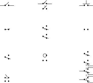
Older convention
Connected Not connected
Newer convention
Connected Not connected
Older electrical schematics showed connecting wires crossing, while non-connecting wires "jumped" over each other with little half-circle marks. Newer electrical schematics show connecting wires joining with a dot, while non-connecting wires cross with no dot. However, some people still use the older convention of connecting wires crossing with no dot, which may create confusion.
For this reason, I opt to use a hybrid convention, with connecting wires unambiguously connected by a dot, and non-connecting wires unambiguously "jumping" over one another with a half-circle
115

116 |
CHAPTER 9. CIRCUIT SCHEMATIC SYMBOLS |
mark. While this may be frowned upon by some, it leaves no room for interpretational error: in each case, the intent is clear and unmistakable:
Convention used in this book
|
Connected |
|
Not connected |
|||
|
|
|
|
|
|
|
|
|
|
|
|
|
|
|
|
|
|
|
|
|
|
|
|
|
|
|
|
|
|
|
|
|
|
|
|
|
|
|
|
|
|
9.2Power sources
DC voltage |
DC voltage |
AC voltage |
+
−
Variable |
|
DC voltage |
DC current |
A diagonal arrow |
+ |
|
|
represents variability |
|
for any component! |
- |
Generator |
AC current |
Gen |
|

9.3. RESISTORS |
117 |
9.3Resistors
Fixed-value Rheostat
Potentiometer Tapped Thermistor
 to
to
Photoresistor
9.4Capacitors
Non-polarized |
Polarized (top positive) |
||||||||||||||||||||
|
|
|
|
|
|
|
|
|
|
|
|
|
+ |
|
|
|
|
|
|
|
|
|
|
|
|
|
|
|
|
|
|
|
|
|
|
|
|
|
|
|
|||
|
|
|
|
|
|
|
|
|
|
|
|
|
|
|
|
|
|
|
|
||
|
|
|
|
|
|
|
|
|
|
|
|
|
|
|
|
|
|
|
|
|
|
|
|
|
|
|
|
|
|
|
|
|
|
|
|
|
|
|
|
|
|
|
|
Variable

118 |
CHAPTER 9. CIRCUIT SCHEMATIC SYMBOLS |
9.5Inductors
Fixed-value |
Iron core |
Variable Variac Tapped
9.6Mutual inductors
Transformer |
Step-up/step-down |
Variac |
||||||||||
transformer |
||||||||||||
|
|
|
|
|
|
|
|
|
|
|
|
|
|
|
|
|
|
|
|
|
|
|
|
|
|
|
|
|
|
|
|
|
|
|
|
|
|
|
|
|
|
|
|
|
|
|
|
|
|
|
|
|
|
|
|
|
|
|
|
|
|
|
|
|
|
|
|
|
|
|
|
|
|
|
|
|
|
|
|
|
|
|
|
|
|
|
|
|
|
|
|
|
|
|
|
|
|
|
|
|
|
|
|
|
|
|
|
|
|
|
|
|
|
|
|
|
Saturable
Transformer Transformer Transformer reactor
Synchro
Synchro
9.7. SWITCHES, HAND ACTUATED |
119 |
9.7Switches, hand actuated
SPST toggle |
|
|
|
|
|
Pushbutton |
|
DPST toggle |
|||||||
normally open |
normally open |
||||||
|
|
|
|
|
|
|
|
|
|
|
|
|
|
|
|
|
|
|
|
|
|
|
|
|
|
|
|
|
|
|
|
|
|
|
|
|
|
|
|
|
|
|
|
|
|
|
|
|
|
|
|
|
|
|
|
|
|
|
|
SPST toggle |
|
|
|
|
|
|
|
Pushbutton |
|||||||||||
|
|
|
|
|
|
|
|||||||||||||
|
|
|
|
|
|||||||||||||||
normally closed |
|
|
|
|
|
|
|
normally closed |
|||||||||||
|
|
|
|
|
|
|
|||||||||||||
|
|
|
|
|
DPDT toggle |
||||||||||||||
|
|
|
|
|
|
|
|
|
|
|
|
|
|
|
|
|
|
|
|
|
|
|
|
|
|
|
|
|
|
|
|
|
|
|
|
|
|
|
|
|
|
|
|
|
|
|
|
|
|
|
|
|
|
|
|
|
|
|
|
|
|
|
|
|
|
|
|
|
|
|
|
|
|
|
|
|
|
|
|
|
|
|
|
|
|
|
|
|
|
|
|
|
|
|
|
|
|
|
|
|
|
|
|
|
|
|
|
|
|
|
|
|
|
|
|
|
|
|
|
|
|
|
|
|
|
|
|
|
|
|
|
|
|
|
|
|
|
|
|
|
|
|
|
|
|
|
|
|
|
|
|
|
|
|
|
|
|
|
|
SPDT toggle |
SPST joystick |
|||||||
position of dot |
||||||||
|
|
|
|
|
|
|
||
|
|
|
|
|
|
|
on circle indicates |
|
|
|
|
|
|
|
|
joystick direction |
|
|
|
|
|
|
|
|
||
4PDT toggle