

Buffering is also a good technique for reducing the loading on a transmission line. For example, where there are ten plug-in cards each with ten ICs, all receiving one signal, their combined load capacitance can be around 400pF. The signal and return currents for this high value of capacitance have a long way to flow, increasing the likelihood that they will create EMC problems. Buffering the signal at each card means that the main line is only loaded by around 40pF, while the signal and return currents for the ten devices on each card now flow only in that card, improving signal integrity and reducing EMC problems.
Carrying high-speed signals through connectors and backplanes, it is important (vital for transmission lines) to maintain the same physical structure. For example, striplines in plug-in boards should be continued as striplines in the backplane, (although it is possible with some degradation in signal integrity to swap from one type of transmission line to another as long as the track dimensions maintain the same Z0). Where transmission lines entering a backplane connector are routed against a power plane, that power plane should be continued through the connector into a power plane in the backplane and then to the associated power planes in the other cards using that signal. The interconnections between the power planes in the boards and the backplane should be designed in the same way as for the 0V return planes. Some boards may find that their optimum backplane connector pinning needs to be: 0V, signal 1, +5V, signal 2, 0V, signal 3, +5V, signal 4, 0V, ….etc.
5.5.7Segregation in backplane systems
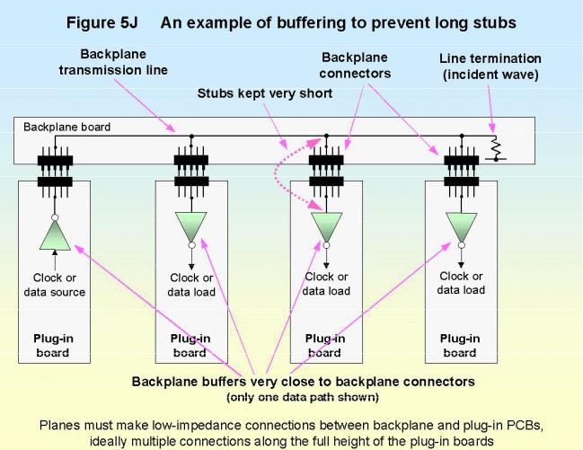
Section 5.1 above said high-speed devices should be kept in the middle of their segregated area, well away from any PCB or reference plane edges, or connectors. The backplane system described above and in Figure 5J places the fastest ICs close to the backplane connector but does not
Design techniques for EMC– Part 5: PCBs |
Cherry Clough Consultants Feb 2000 Page 23 of 24 |