

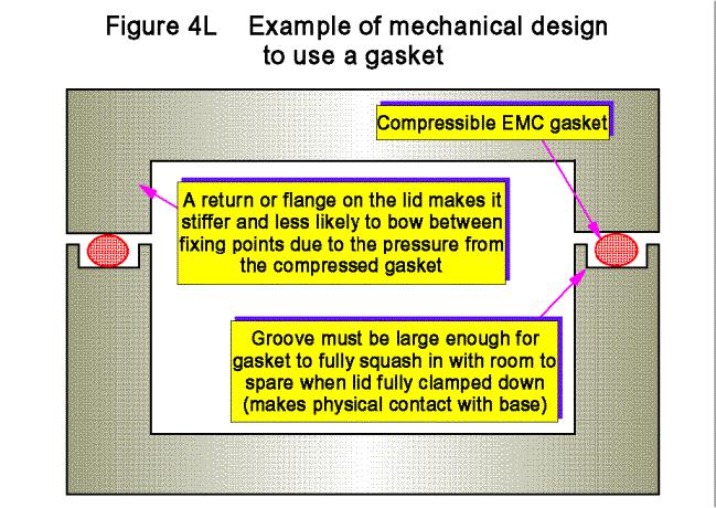
Gasket contact areas must not be painted (unless it is with conductive paint), and the materials used and their preparation and plating must be carefully considered from the point of view of galvanic corrosion.
All gasket details and measures must be shown on manufacturing drawings, and all proposed changes to them assessed for their impact on shielding and EMC. It is not uncommon, when painting work is transferred to a different supplier, for gaskets to be made useless because masking information was not put on the drawings. Changes in the painting processes used can also have a deleterious effect (as can different painting operatives) due to varying degrees of overspray into gasket mounting areas which are not masked off.
4.9Shielding of displays (and the like)
Displays require apertures in enclosures, compromising shielding. A few small LEDs usually present few problems (although when using plastic enclosures they are often a weak spot for personnel ESD susceptibility). Mounting a display outside a shielded enclosure avoids the aperture, but removes the benefit of the shielding from the display and creates the new problem of what to do with the display’s data and power cables and their penetration of the enclosure.
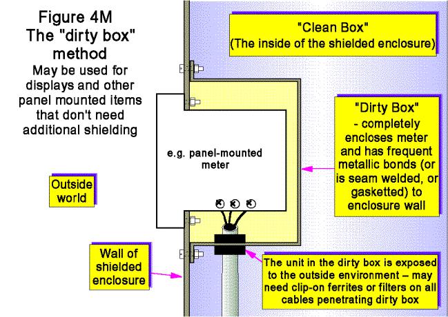
Figure 4M shows a display unit mounted in a large aperture in the wall of the shielded enclosure, using an internal “dirty box” to control the field leakage through the aperture. The joint between the dirty box and the inside of the enclosure wall must be treated the same as any other joint in the shield.
Design techniques for EMC – Part 4 – Shielding |
Cherry Clough Consultants |
Page 16 of 23 |
Shielded windows are needed where a display needs shielding by a product’s enclosure. Some high-grade CRTs can provide a good shield when the metal frame around the front of their tube is electrically bonded to the front panel all around the aperture. Active matrix LCDs upgrades to products which had used high-grade CRTs have been known to be the cause of more emissions than the CRTs, and some have needed additional shielded windows where the CRTs had not.
A variety of shielded windows are available, based on two main technologies:
♦Thin metal films on plastic sheets, usually indium-tin-oxide (ITO). At film thicknesses of 8 microns and above optical degradation starts to become unacceptable, and for battery-powered products the increased backlight power may prove too onerous. Referring to figure 4A, we see that the thickness of these films may be insufficient to provide good SEs below 100MHz.
♦Embedded metal meshes, usually a fine mesh of blackened copper wires. For the same optical degradation as a metal film these provide much higher SEs, but they can suffer from Moiré fringing with the display pixels if the mesh is not sized correctly. One trick is to orient the mesh diagonally.
Honeycomb metal display screens are also available for the very highest shielding performance. These are large numbers of waveguides below cutoff, stacked side by side, and are mostly used in security or military applications where their extremely narrow viewing angle means that the operator’s head prevents anyone else from sneaking a look at their displays.
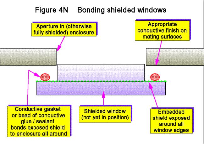
A vital issue for screened windows is that their conducting layers (mesh, film, or honeycomb metal) must be bonded directly to the enclosure shield surface around all the edges of their cut -out.
Figure 4N shows one typical assembly method, which can use a conductive sealants / glues to avoid the need for mechanical fixings. The use of UV-curable conductive adhesives can make assembly times equal or better mechanical fixing methods.
Design techniques for EMC – Part 4 – Shielding |
Cherry Clough Consultants |
Page 17 of 23 |
4.10Shielding ventilation apertures
This presents similar issues to the shielding of displays, but only meshes or waveguides below cutoff can be used. As above, these must be bonded metal-to-metal (or with conductive gaskets) to the enclosure shield all around their ventilation aperture. Mesh size can of course be much coarser than for display applications, and expanded metal is sometimes used.
The mesh size must be small enough not to reduce the enclosure’s SE too much. The SE of a number of small identical apertures near to each other is (roughly) proportional to their number, n, (∆SE = 20logn), so two apertures will make SE worse by 6dB, four by 12dB, 8 by 18dB, and so on. For a large number of small apertures typical of a ventilation grille, mesh size will be considerably smaller than one aperture on its own would need to be for the same SE. At higher frequencies where the size of the ventilation aperture exceeds one-quarter of the wavelength, this crude “6dB per doubling” formula can lead to over-engineering, but no simple rule of thumb exists for this situation.
Waveguides below cutoff allow high air flow rates with high values of SE, and honeycomb metal ventilation shields (consisting of many long narrow hexagonal tubes bonded side-by-side) have been used for this purpose for many years. It is believed that at least one manufacturer of highly shielded 19” rack cabinets claims to use waveguide below cutoff shielding of the top and bottom ventilation apertures using ordinary sheet metalwork techniques.
The design of shielding for ventilation apertures can be complicated by the need to clean the shield of the dirt deposited on it from the air. Careful air filter design can allow ventilation shields to be welded or otherwise permanently fixed in place.
Design techniques for EMC – Part 4 – Shielding |
Cherry Clough Consultants |
Page 18 of 23 |
4.11Shielding with painted or plated plastics
Plastic enclosures are often used for a pleasing feel and appearance, but can be difficult to shield. Coating the inside of the plastic enclosure with conductive materials such as metal particles in a binder (conductive paint), or with actual metal (plating), is technically demanding and requires attention to detail during design of the mould tooling if it is to stand any chance of working.
It is often found – when it is discovered that shielding is necessary – that the design of the plastic enclosure does not permit the required SE to be achieved by coating its inner surfaces. The weak points are usually the seams between the plastic parts: they often cannot ensure a leak-tight fit, and usually cannot easily be gasketted. Expensive new mould tools are often needed, with consequent delays to market introduction and to the start of income generation from the new product.
Whenever a plastic case is required for a new product, it is financially vital that consideration be given to achieving the necessary SE right from the start of the design process.
Paint or plating on plastic can never be very thick, so the number of skin-depths achieved can be quite small. Some clever coatings using nickel and other metals have been developed to take advantage of nickel’s reasonably high permeability to reduce skin depth and achieve better SE.
Other practical problems with painting and plating include making them stick to the plastic substrate over the life of the product, in its intended environment. Not easy to do without expert knowledge of the materials and processes. Conductive paint or plating flaking off inside a product can do a lot more than compromise EMC – it can short conductors out, causing unreliable operation and risking fires and electrocution. Painting and plating plastics must be done by experts with long experience in that specialised field.
A special problem with painting or plating plastics is voltage isolation. For Class II products (double insulated) adding a conductive layer inside their plastic cases can reduce creepage and clearance distances and compromise electrical safety. Also, for any plastic-cased product, adding a conductive layer to the internal surface of the case can encourage personnel electrostatic discharge (ESD) to occur through seams and joints, possibly replacing a problem of radiated interference with one of susceptibility to ESD. For commercial reasons it is important that careful design of the plastic enclosure occurs from the beginning of the design process, if there is any possibility that shielding might eventually be required.
Some companies box clever (pun intended) by using thin and unattractive low-cost metal shields on printed circuit boards or around assemblies, making it unnecessary for their pretty plastic case to do double duty as a shield. This can save a great deal of cost and headache, but must be considered from the start of a project or else there will be no room available (or the wrong type of room) to fit such internal metalwork.
4.12Shielding without metal
Volume-conductive plastics or resins generally use distributed conductive particles or threads in an insulating binder which provides the mechanical strength. Sometimes these suffer from forming a “skin” of the basic plastic or resin, making it difficult to achieve good RF bonds without helicoil inserts or similar means. These insulating skins make it difficult to prevent long apertures being created at joints, and also makes it difficult to provide good bonds to the bodies of connectors, glands, and filters. Problems with the consistency of mixing conductive particles and polymer can make enclosures weak in some areas, and lacking in shielding in others.
Materials based on carbon fibres (which are themselves conductive) and self-conductive polymers are starting to become available, but they do not have the high conductivity of metal and so do not give as good an SE for a given thickness.
Design techniques for EMC – Part 4 – Shielding |
Cherry Clough Consultants |
Page 19 of 23 |