


Through-bulkhead filters are best, but may be too expensive for some applications, such as mains currents above 10A (the maximum rating of the IEC 320 style mains connector). For higher powers most commercially available mains filters are just rectangular units with screw-terminal connections. Figure 3G shows how to mount such filters using the "dirty-box" method, which encloses the filter in its own box within the main shielded enclosure (the “clean box”) to help achieve good highfrequency performance.
The filter input and output cables in the dirty box must be very short and far away from each other, but even so, very high frequencies may still couple between them and soft-ferrite cylinders may be needed on either (or both) cables.
Filters which are not through-bulkhead types but must have the highest performance often deal with cable coupling by enclosing their input and output terminals inside their metal enclosure (a “dirty box”) and bringing their cables out through standard circular galvanised conduit fittings. Running the cables in conduit effectively shields the unfiltered from the filtered cables, and the filter functions effectively up to the highest frequencies. This is the method used by most of the supply filters intended for EMC test chamber applications. Input and output cables may be screened instead of being run in conduit for the same effect.
3.14Surge protection devices (SPDs)
3.14.1Types of SPD
Surge arrestors are variable resistance devices, whose resistance is a function of the applied voltage. They are designed so that they provide a clamping effect when the voltage across them exceeds a certain level, rather like a zener diode.
There are four basic types of SPD:
Design techniques for EMC – Part 3 |
Cherry Clough Consultants June 99 |
Page 13 of 19 |
•Gas discharge tube (GDT), essentially just a spark gap, slow but very high power
•Metal-oxide varistor (MOV), fast and available in a wide range of energy ratings
•Avalanche devices, semiconductors with a zener type action, very fast but not very high power
•SCR devices, another type of semiconductor device, slow but will handle high currents
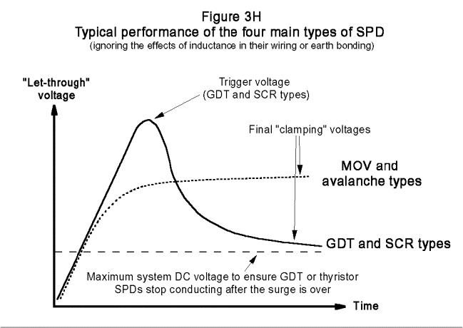
Figure 3H sketches the voltage/time curves of these four types of SPD when exposed to the leading edge of a typical surge test waveform. It shows that GDT and SCR devices are slow to start suppressing. They have to reach a trigger voltage before they begin to conduct, and during this time they let through surge voltages which may be potentially damaging. They also have a foldback characteristic, which means that once they are triggered and are carrying current, the voltage across them drops to well below the voltage they were previously quite happy to block. Consequently, careful design is needed to make sure that when they are connected to a source of DC current they do not remain in conduction for ever.
MOV and Avalanche devices act like zener diodes, with a knee voltage where they start to draw current. As their current increases their clamping voltage rises slowly.
The wired-in SPDs usually used for mains suppression may be unsuitable for use on signal or data lines, because of too much leakage, or too much capacitance, or impedance mismatch, or a variety of other problems. Special SPDs are available fitted with connectors intended to plug directly into a wide variety of digital and analogue signal cables and be mounted to earthed metalwork, like through-bulkhead filters. Radio antenna and high-speed data lines use matched transmission-line type SPDs, which use connectors such as BNCs.
3.14.2Are SPDs needed on data lines?
SPDs are often advertised for use on data lines, but this is only really necessary on long cables which remain within a building, where there is a poor earth structure between the equipments at
Design techniques for EMC – Part 3 |
Cherry Clough Consultants June 99 |
Page 14 of 19 |
each end such that lighting surges can cause a high voltage to appear between them. Where a product’s cables exit a building (or connect to an external antenna) they should always have surge protection fitted.
For short interconnections (for example between keyboards or printers and PCs) the problems of earth voltage surge differences and fast transient bursts does not exist, and all that is left for an SPD to act on are electro-static discharge (ESD) transients. We shall see in Part 6 that ESD is best dealt with by using plastic to prevent discharges altogether, or else using good earth-bonding of metalwork.
3.14.3SPDs and data integrity
Surge protection of analogue or digital data is usually not complete in itself. Even though the surges do not cause damage, they will have given a false value or bit. Where no memory or program is involved, as in simple analogue indicating instruments, a momentary glitch in the reading may be acceptable (depending on function), but for some analogue signals and all digital data (such as control signals) a momentarily incorrect signal can alter the stored data or operational mode, and this is usually unacceptable. Very slow data may be able to use filtering to reduce the “spike” to below detection thresholds.
Where glitched data is not acceptable and yet the only protection from surges is the use of SPDs, there needs to be some way of identifying and recovering from the incorrect data. Communication protocols are the usual answer, briefly mentioned Part 1.4.7. There are a number of these, ranging from simple to exotic, all with various overheads and penalties, and it is by far the best to buy the chips which implement protocols proven to be robust in real-life applications (e.g. CAN) rather than imagine that you can create a protocol of your own that will be good enough, even for the most costsensitive high-volume applications.
3.14.4Ratings of SPDs
SPD ratings should really be chosen in conjunction with the design of a building and its lightning protection network. BS6651 Appendix C deals with this issue, and specifies the SPD ratings for equipment fitted in different parts of a building.
This standard, or others which deal with the lightning protection of electronic equipment (e.g. IEEE C62.41–1991) should be used where the generic or product EMC standards are lacking in surge requirements, or where their surge requirements are incomplete (for example, EN50082-1:1992 and EN 50082-2:1995 have no surge requirements at all, whereas EN 50082-1:1997 only applies surge requirements to mains and DC power ports).
BS6651 Appendix C specifies the following SPD ratings for the mains supply for equipment located more than 20 metres from the building’s incoming mains connection (the most benign location, known as Category A):
•
•
•
Low risk premises: |
2kV, 167 Amps |
Medium risk premises: |
4kV, 333 Amps |
High risk premises: |
6kV, 500 Amps |
Buildings not large enough to have a Category A, which includes most residences, are specified as Category B for internally connected equipment:
•
•
•
Low risk premises: |
2kV, 1,000 Amps |
Medium risk premises: |
4kV, 2,000Amps |
High risk premises: |
6kV, 3,000 Amps |
External telecommunication and other signal/data cables (no matter how far they travel within a building), and the mains supplies to equipment mounted outside a building, are known as Category C:
Design techniques for EMC – Part 3 |
Cherry Clough Consultants June 99 |
Page 15 of 19 |
•
•
•
Low risk premises: |
6kV, 3,000 Amps |
Medium risk premises: |
10kV, 5,000Amps |
High risk premises: |
20kV, 10,000 Amps |
When a product is adequately protected against lightning surges, it is generally protected well enough against common surges generated by other means, such as switchgear. Where an application is known or suspected of suffering high levels of surges not of lightning origin, it is generally enough to protect the product to the next higher level of surge than is called for by the lightning protection standards.
Some superconducting magnet or power generation applications, or Nuclear Electromagnetic Pulse (NEMP) involve extreme or special types of surges, and are not addressed here.
3.14.5Fusing of SPDs
All SPDs fail eventually, and since the majority of products use metal-oxide-varistor types (whose failure mode is to leak increasingly and finally to go short-circuit) in their mains inputs, they may need to be fused to prevent fire or shock hazards.
If the fuse is in the SPD circuit only, when it opens during the surge event that kills the SPD the protected equipment may be exposed to the remaining parts of the surge and damaged. Afterwards, even if the protected equipment is undamaged, it has lost its surge protection and so is very exposed to the next surge that comes along.
If the fuse is in series with the line that also goes to the protected equipment, the opening of the fuse due to SPD failure will disconnect the line to the equipment, which may not be acceptable in critical applications.
There is no easy answer to the problem of SPD fusing, but either of the above methods are generally acceptable providing the SPD is adequately rated for a goodly number of the maximum surges expected to be experienced. Once again, the lighting protection standards come to our aid, with risk assessments based on geography and application which allow the number and magnitude of surges caused by lightning to be assessed so that long-term reliability is likely.
Design techniques for EMC – Part 3 |
Cherry Clough Consultants June 99 |
Page 16 of 19 |