- •Filter design, selection, and installation
- •How filters work
- •The advantages of soft ferrites
- •Inductance variation with current
- •Determining filter specifications
- •Earth leakage currents, and safety
- •Issues of frequency and/or sensitivity of wanted signals
- •Filter earthing
- •The synergy of filters and shielding
- •Filter construction, mounting, and cabling
- •Surge protection devices (SPDs)
- •Types of SPD
- •Are SPDs needed on data lines?
- •SPDs and data integrity
- •Ratings of SPDs
- •Fusing of SPDs
- •Assembly of SPDs
- •The problems of earth lift
- •Further reading

Design Techniques for EMC – Part 3
Filters and Surge Protection Devices
By Eur Ing Keith Armstrong CEng MIEE MIEEE
Partner, Cherry Clough Consultants, Associate of EMC-UK
This is the third in a series of six articles on best-practice EMC techniques in electrical/electronic/mechanical hardware design. The series is intended for the designer of electronic products, from building block units such as power supplies, single-board computers, and “industrial components” such as motor drives, through to stand-alone or networked products such computers, audio/video/TV, instruments, etc.
The techniques covered in the six articles are:
1)Circuit design (digital, analogue, switch-mode, communications), and choosing components
2)Cables and connectors
3)Filters and transient suppressors
4)Shielding
5)PCB layout (including transmission lines)
6)ESD, electromechanical devices, and power factor correction
A textbook could be written about any one of the above topics (and many have), so this magazine article format can do no more than introduce the various issues and point to the most important of the best-practice techniques. Many of the techniques described in this series are also important for improving signal integrity, reducing the number of iterations during development, and reducing manufacturing costs.
Table of contents for this part
3.Filters and surge protection devices
3.1Filter design, selection, and installation
3.2How filters work
3.3The advantages of soft ferrites
3.4Common-mode (CM) and differential mode (DM)
3.5Crude filter rules-of-thumb
3.6Inductance variation with current
3.7Determining filter specifications
3.8Problems with real-life impedances
3.9Earth leakage currents, and safety
3.10Issues of frequency and/or sensitivity of wanted signals
3.11Filter earthing
3.12The synergy of filters and shielding
3.13Filter construction, mounting, and cabling
3.14Surge protection devices (SPDs)
3.14.1Types of SPD
3.14.2Are SPDs needed on data lines?
3.14.3SPDs and data integrity
3.14.4Ratings of SPDs
Design techniques for EMC – Part 3 |
Cherry Clough Consultants June 99 |
Page 1 of 19 |
3.14.5Fusing of SPDs
3.14.6Assembly of SPDs
3.14.7The problems of earth lift
3.15Further reading
3.Filters and surge protection devices
Filters are used to attenuate unwanted frequencies travelling along conductors, and are characterised by attenuation versus frequency curves. Surge protection devices (SPDs) attenuate unwanted voltage surges travelling along conductors, and are characterised by graphs of voltage “let-through” versus time.
Incorrect use of filters or SPDs can make a product’s emissions or immunity worse than if they were not used at all. More expensive filters or SPDs are not necessarily the best. You cannot in general choose a filter or SPD from a distributor’s catalogue, only checking its ratings, number of circuits, and intended application, and expect it to provide the benefits you want.
3.1Filter design, selection, and installation
The design and/or selection of filters can seem like a black art. It is not, but even when all the best efforts have been made along the lines described here, it is usually still necessary to try out a number of filters to find the optimum.
There are many books written on filter design. I have found Arthur B Williams book “Electronic Filter Design Handbook” very useful (McGraw Hill, 1981, ISBN 0-07-070430-9). No doubt there is a more modern edition available, but filter design has not changed much over the years. There are now a number of filter simulators which run happily on PCs.
I am not going to go into filter design in this article – but I will describe the things which need to be taken into account so that filters designed using textbooks, simulation programs, or chosen from catalogues, stand a chance of performing as required.
This article assumes that we are discussing filters to be fitted at the boundary between a product and its external environment. Filters for use inside a product, for example between a switch-mode power supply and a sensitive circuit, will share some if not all of the same considerations.
3.2How filters work
A filter that works well in one situation can be poor in a different one, so we need at least a basic understanding of how filters work.
Filters work by creating a discontinuity in the impedance seen by a signal travelling along a conductor. The greater the discontinuity, the greater the attenuation. So if the impedance of an unwanted signal is 100Ω and we put a 1kΩ impedance in series with it, only about 10% of the signal gets through the high impedance – an attenuation of around 20dB. A similar effect can be created by instead shunting the 100Ω conductor with a low impedance: 10Ω would also provide an attenuation of around 20dB.
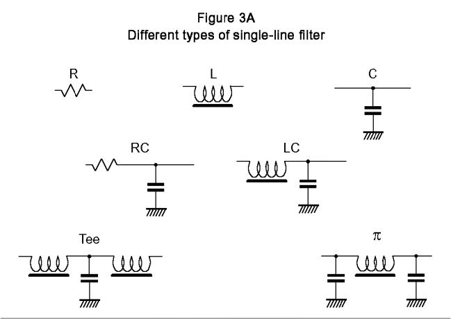
A variety of basic EMC (low-pass) filter types is shown in Figure 3A. Simple R-only and L-only filters create a series high impedance and are best used where the impedance of the unwanted signals is low. C-only filters create a shunt low impedance and so are best used where the impedance of the unwanted signals is high. Data sheet figures for C-only filters are rarely achieved in real life because they rely on the RF integrity of their earths (ideally zero impedance over all frequencies), and this is never achieved in reality.
Design techniques for EMC – Part 3 |
Cherry Clough Consultants June 99 |
Page 2 of 19 |

Resistors eventually lose their performance at high frequencies due to their stray shunt capacitance. Inductors also suffer from stray shunt capacitance, and this causes self-resonance and limits their high-frequency performance. The best inductors for EMC filter use have closed magnetic circuits (such as toroids, cylinders, etc., and other shapes with no air gaps), unfortunately this means that they are more likely to suffer from saturation effects at high currents (discussed later).
Capacitors suffer from intrinsic inductance, plus lead inductance, causing self-resonance and limiting high-frequency performance. The three-leaded capacitor has fewer problems with inductance (as long as its “earthy” lead is very short), but the ultimate elimination of inductive effects is only achieved by the feed-through capacitor, which has excellent high-frequency behaviour. Traditional feed-through capacitors are soldered or screwed into a shield wall, but some surfacemount devices now offer similar benefits when soldered to a PCB ground plane.
RC filters are the most predictable of all EMC filters because they do not resonate strongly. High values of R are best (say, from 1 to 10 kΩ) with low values of C (say 10nF or less). The most common use for RC filters is where a DC or low frequency signal from a low-ish source impedance is input to a high impedance circuit (the R connected to the source side, the C connected to the circuit side), and in these applications they can reliably provide very high attenuation at lowest cost.
LC, tee, and π filters can provide higher levels of attenuation with lower losses than filters using resistors, but are resonant circuits and are more sensitive to the impedances they are connected to.
Tee filters using resistors (RCR) are increasingly used to connect computer motherboards to displays and other peripherals which use a high data rate via ribbon cables or flexi-circuits. These are really C-only filters – the resistors are for terminating the transmission lines on either side of the capacitor to maintain signal integrity. The resistors are usually in the range 22 to 100Ω, and the filters are usually fabricated as arrays in small outline surface mount packages.
Design techniques for EMC – Part 3 |
Cherry Clough Consultants June 99 |
Page 3 of 19 |

3.3The advantages of soft ferrites
LC, tee, and π filters also suffer from the imperfections intrinsic to inductors and capacitors and their leads, which are a significant cause of the differences between simple calculations (or simulations) and real life. The use of soft ferrites for EMC filter inductors helps to ease these problems.
Soft ferrites are inductors at low frequencies, but become lossy (resistive) at higher frequencies. When used as an L-only filter soft ferrites usually provide between 3 and 20dB attenuation on typical cables, without significant resonances. When used in more complex filters, soft ferrites provide much more predictable performance (although some simulators may be unable to model their complex impedance-versus-frequency behaviour). Standard soft ferrite materials for EMC applications are still effective at 1,000MHz, with some recent components extending this to 2GHz.
A very wide range of soft ferrite RF suppression components exist, and are continually being added to, and recent offerings include SMD parts which provide 1kΩ or more around 100MHz, yet have DC resistances under 0.1Ω and are rated at 3A continuous. Choosing the right soft ferrite requires checking their impedance versus frequency graphs for the desired resistive impedance over the required frequency range. A true soft ferrite has no discontinuities in its impedance plot.
3.4Common-mode (CM) and differential mode (DM)
To use filters effectively we need to know which conductors to connect our filter elements to, so we need to know the difference between common-mode and differential mode.
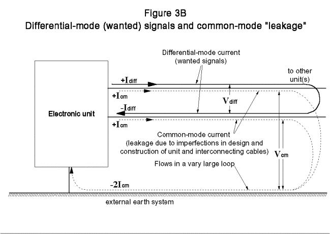
Figure 3B shows that wanted signals are almost always DM: the current flows out on one defined conductor, back on another, and these two conductors have a voltage between them. Sometimes more than two conductors are required for a signal and all of its current return paths (e.g. +5, signal, 0V; three-phase AC power), but the principle is the same.
Design techniques for EMC – Part 3 |
Cherry Clough Consultants June 99 |
Page 4 of 19 |

On the other hand, CM voltages and currents are identical for all the conductors in a cable (including any screens), and all CM currents flow in the same direction. The return path for CM currents is via the external earth system, other cables, metalwork, etc. CM currents and voltages are often very small in amplitude, but their large loop areas create worse EMC problems than equivalent DM signals.
CM is almost without exception caused by imperfections in design and construction which convert a fraction of the wanted (DM) signals to CM, causing problems with emissions. These same imperfections also convert a fraction of external CM interference into DM signals, worsening signal- to-noise ratios and/or digital signal integrity and causing problems with immunity. Cables are a significant contributor of DM to CM conversion, and the measure of this is called their “longitudinal conversion loss”.
The powerful digital integrated circuits (ICs) used in many modern products create a lot of internal high-frequency switching noise due to ground and power “bounce”. This leaks out of the ICs on all their connections and couples to PCB tracks, eventually appearing on I/O and all other cables as CM noise. This noise has a much higher frequency content and amplitude than would be expected from knowledge of the wanted signals, so is difficult to predict and is usually only quantified by measurement. (The techniques described in Part 1.1 and Part 5 will reduce this noise considerably.)
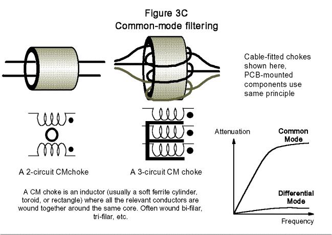
When a magnetic circuit (such as a ferrite toroid) is wrapped around a single conductor, it will attenuate all the currents in it, whether DM or CM. But when a magnetic circuit is wrapped around both (or all) the send and return conductors associated with a differential signal or power circuit, it will only attenuate CM currents. The magnetic fluxes created by the DM send and return current paths cancel out in a CM inductor, so (ideally) it has no effect on the wanted signal or power. In practice there is always some leakage inductance, hence always some attenuation of DM currents, and this can be used to provide both CM and DM filtering in one component. Figure 3C shows some aspects of common-mode choke filters.
Design techniques for EMC – Part 3 |
Cherry Clough Consultants June 99 |
Page 5 of 19 |

For most EMC work, common-mode chokes are made from soft ferrite. The cancellation of DM flux in CM chokes (often called a current-balanced choke) allows large inductance values (milliHenries) to be achieved with small components, whereas DM chokes the same size are measured in microHenries, and become physically larger as currents increase.
Wrapping a set of conductors several times around the same magnetic circuit increases CM impedance, but is not effective at high frequencies because stray capacitances “short out” the choke. For higher attenuation at very high frequencies it is better to string a number of ferrite tubes or toroids along a cable, with only one pass of the cable through each. (Surface mounted ferrite beads can achieve high impedances at high frequencies because their parasitic capacitances are so small.)
A useful soft ferrite component is a cylinder split lengthways and held in a plastic “clip-on” housing. They are very easy to apply to cables (and to remove when found not to do much), and are available in a wide range of shapes and sizes, including flat type for ribbon cables. All EMC engineers’ carry many of these with them, using them for diagnosis and isolation of EMC problems, as well as cures.
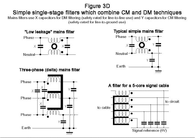
Figure 3D shows how common-mode and differential-mode filtering is combined in a number of simple filters.
3.5Crude filter rules-of-thumb
So we can now define our crude filter rules-of-thumb:
•If unwanted signal is high impedance and DM, attenuate with a shunt capacitor (connected between its send and return conductors)
Design techniques for EMC – Part 3 |
Cherry Clough Consultants June 99 |
Page 6 of 19 |
