

the electronic technology in the product, and is unlikely to be adequate for high-performance digital or analogue products. The cable screens would connect 360o to the PCB ground plane.
2.6.6Terminating cable screens at both ends
This seems like heresy to some, but with the high frequencies in use these days leaving an end unterminated will usually leak too much. Screen termination at both ends also allows the screen to work on all orientations of magnetic fields.
Of course, connecting screens at both ends allows any earth potential differences to drive currents in the screen that might cause hum pickup, and even melt the cables. Where such earth currents exist it is an indication of poor facility earth-bonding which could allow earth faults or thunderstorm surges to destroy inadequately protected electronics. It is not unknown for screened cables to flash-over at unterminated ends during thunderstorms, creating obvious hazards.
It is sometimes recommended to electrically bond a cable screen at one end, and terminate the other with a small capacitor. The aim is to prevent excessive power frequency screen currents, and it does work to some extent although it is difficult to get capacitors to provide low enough inductance for very high frequencies and it does nothing for surge and flashover problems. Insulated BNC connectors are available with screen-to-chassis capacitors built-in, but the last price I had for types which worked well to 1GHz was nearly £20 each.
Galvanically isolated communications offer a way out of bonding screens at both ends, but such an approach needs careful attention to detail, especially the safety and reliability issues associated with installation earth-faults and surges. Metal-free fibre optics are the best kind of galvanically-isolated signal communications, and the easiest to use.
Section 2.5 above briefly lists the currently accepted best installation practices in achieving good EMC (e.g. using a PEC to divert heavy earth currents) without suffering hot cables and without compromising safety. Refer to IEC 61000-5-2:1997 for more detail.
2.7Getting the best from connectors
Connectors suffer from many of the same EMC problems as cables, after all, they are just short lengths of conductor in a rigid body.
It is best to segregate connectors into those used for internal connections, and those used for outside connections, because of the possibility of flashover from outside to inside pins during surge or electrostatic discharge events. Such flashovers can bypass protective devices.
2.7.1Unscreened connectors
Controlled-impedance transmission-line connectors are increasingly available for high-speed backplanes or cables.
When not using transmission lines, much improved EMC and signal integrity can be had from ordinary multiway connectors (e.g. DIN41612, screw-terminal strips) by making sure that each “send” pin has a return pin alongside. At the very least provide one return pin for every two signals. It is best when these are used with balanced signals, but the technique also helps when signals are singleended.
2.7.2Connectors between PCBs
Connectors between PCBs (e.g. daughterboard to motherboard) also benefit greatly from multiple 0V pins spread over their full length and width, and a similar arrangement of power pins also helps significantly. Optimum signal integrity and EMC is generally achieved (for signals sharing the same power rails) with a pin pattern that goes:
0V, signal, +V, 0V, signal, +V, 0V, signal, +V, 0V, etc.
The following pattern provides lower performance but is often adequate, and uses fewer pins: 0V, signal, +V, signal, 0V, signal, +V, signal, 0V, etc.
It is also best to extend the connector over the full length of the common edge between the two boards, and liberally sprinkle 0V and power connections over the full length. There is some evidence
Design techniques for EMC – Part 2 – Cables and connectors |
Cherry Clough Consultants March 99 |
Page 15 of |
that random pin allocations may provide better performance by breaking up standing wave patterns. Additional grounds between sensitive and noisy signals can help be a barrier to crosstalk.
We don’t really like connectors on PCBs, and they should be avoided if possible (reliability will improve as a result) – as mentioned earlier, single or flexi-rigid PCBs with ground planes under all their tracks are better. Also: don’t socket ICs (use field programmable PROMS). Each IC socket pin is a little antenna positioned right at the most vulnerable or noisy location possible.
2.7.3Screened connectors
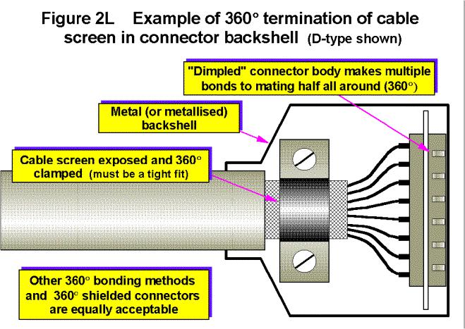
There is no such thing as a connector that “complies with the EMC Directive”, there are only connectors with frequency-dependant screening performance. Screened cables must maintain 360o screen coverage over their whole length, including the backshells of their connectors at both ends. Connector backshells must make 360o electrical bonds to the enclosure shields they are mounted on, using iris springs or some other method. Saddle-clamps seem to make adequate screen bonds for most purposes in rectangular connector backshells, but avoid the ones that need the screen to made into a pigtail, however short. Figure 2L shows a typical D-type screen termination.
Co-axial and twinaxial screened cables benefit most from connectors with screwed metal backshells. These are better and more reliable at high frequencies than bayonet types (like BNC), which is why they are used on satellite TV convertor boxes.
Multiway screened cables are also best used with round connectors with screwed backshells, but are often specified with rectangular connectors such as D-types or larger. Making a 360o connection from cable screen to connector backshell, and from backshell to enclosure shield, seems a lot to ask of some connector manufacturers, so check this has been done effectively before committing to a particular make or type. Especially watch out for single (or long) springs, clips, and wires, when used to make a screen bond: these are just pigtails and will limit SE at high frequencies.
Unfortunately, many industry-standard connectors do not allow correct termination of cable shields (e.g. jack plugs, XLRs, phonos, and any number of proprietary connector models). Also unfortunately,
Design techniques for EMC – Part 2 – Cables and connectors |
Cherry Clough Consultants March 99 |
Page 16 of |