

causing the product to fail conducted or radiated emissions tests depending on signal frequency. Any filtering would need to remove the signal, which does not help.
Filtering can work quite effectively for low-frequency analogue signals, but for precision beyond ±0.05% (12 bits) the cost of the filter and its board area increases rapidly. Of course filters have difficulty removing in-band interference (such as powerline hum) that a properly designed balanced communication system would easily reject.
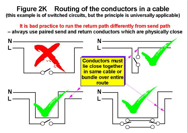
2.6.3Pairing send and return conductors
Even when not using transmission lines, always use paired conductors. Provide a dedicated return path for the return current as close as possible to the send path (and not via an earth or a screen). This works even when signals are single-ended and all their return conductors are bonded to a common reference potential. The fluxcompensation effect encourages return currents to flow in the path nearest to the send conductor, in preference to alternative current paths, and we can use this natural phenomenon to help keep the field patterns of our cables tight and reduce their E and M leakages. Figure 2K shows the general principle, which is of universal application.
Figure 2K shows a mains supply with a switch in one line, but the same principle applies to signals.
The closeness of the send and return conductors over the entire current loop is absolutely crucial at the highest frequencies for circuits to work at all, never mind good EMC.
Ribbon cables carrying a number of single-ended (i.e. 0V referenced) signals are very poor indeed for EMC and signal integrity, but screening them results in stiff, bulky, expensive cable assemblies which is what flat cables were supposed to avoid.
Using the pairing technique for flat cables improves their EMC considerably and this conductor arrangement is the best:
return, signal, return, signal, return, etc.
Design techniques for EMC – Part 2 – Cables and connectors |
Cherry Clough Consultants March 99 |
Page 12 of |
A less effective alternative which is often recommended is:
return, signal, signal, return, signal, signal, return, etc.
Significant improvements can often be made by fitting flat cable ferrite clamps (common-mode chokes) at the source end(s), so that the conductor pairs behave as if they were driven from a balanced source at high frequencies, although proper balanced drive/receive circuits are better (see Part 1 of this series).
Twisted pairs are very much better than parallel pairs. Use twisted triples, quads, etc. where this is what it takes to get all the send and return paths of a signal in close proximity.
Twisted send and return conductors are strongly recommended for power cables: combining all phase and neutral conductors (two for single-phase, three for three-phase, four for three-phase plus neutral) in a single cable with a slow twist greatly reduces the emissions of powerline M field emissions. M fields from power busbars or individually routed phase and neutral cables can render whole areas of buildings unfit for CRT-based VDU monitors.
Twisted pairs using balanced circuitry (see Part 1 of this series) and common-mode chokes can be good for signals up to some tens of MHz, depending on the “balance” of the circuit, cable, and connectors. Any unbalance will convert some of the wanted signal into useless common-mode currents, which all leaks away as fields. Just a few micro-amps of common-mode can fail an emissions test. Tighter and more precisely regular twists make cables better for higher frequencies.
A great many types of twisted-pair cables are available, some intended for transmission lines (Z0 will be specified). But twisted pair technology does not suit mass-termination. So-called “twist + flat” flat cable has multiple twisted pairs all formed into a ribbon, but has regular lengths of 100mm or so of parallel conductors for mass-terminating connectors – and the flat bits are so long they compromise EMC.
2.6.4Getting the best from screened cables: the screen
There is no such thing as a cable that “complies with the EMC Directive”, there are only cables with frequency-dependant screening performance.
Cable screens must cover the entire route with 360o coverage. Making screening work effectively with low-cost these days is increasingly difficult, except for the least aggressive and least sensitive signals.
It is no longer best practice to use the shield of a cable as the signal return. The problem with co-axial cables is that the screen carries currents for both the signal return and external interference, and they use the skin effect to keep them on different sides of the screen (known as “tri-axial mode”). This works fine for solid copper screens (plumbing, to you and me), but flexible screened cables aren’t very good at keeping the two currents apart, so return currents leak out, and interfering currents leak in.
But (I hear you say) all RF test equipment uses flexible co-ax, so it must be OK. Look carefully at these cables next time you are in an EMC test lab: the cables used for higher frequencies are very thick, stiff, and expensive, partly because they are double-screened at least. They use expensive screwed connectors (e.g. N-types), and are always used in matched (at both ends) 50Ω transmission lines. They are also treated reverentially and woe betide you if you tread on one. At higher frequencies than the average EMC test lab, semi-rigid or rigid co-axial cables have to be used, as stiff as automotive brake pipes.
The ability of a screened cable to prevent interference is measured in two ways, as shielding effectiveness (SE), and also as ZT. SE seems obvious enough, and ZT is simply the ratio of the voltage which appears on the centre conductor in response to an external RF current injected into the screen. For a high SE at a given frequency, we need a low ZT. A flat ZT of a few milliΩ over the whole frequency range would be ideal.
A very broad-brush summary of the screening qualities of typical types of screened cables follows, but remember that within each broad category there are many different makes and grades with different performances:
Design techniques for EMC – Part 2 – Cables and connectors |
Cherry Clough Consultants March 99 |
Page 13 of |
•Spiral wrapped foil is not terribly good at any frequency, and gets progressively worse > 1MHz.
•Longitudinal foil wrap is better than spiral foil.
•Single braid is better than foil at all frequencies, but still gets progressively worse > 10MHz.
•Braid over foil, double braid, or triple braid, are all better than single braid and all start to get progressively worse >100MHz
•Two or more insulated screens are better still, but only up to about 10MHz, at higher frequencies resonances between the screens can reduce their effectiveness to that of just one screen at some frequencies.
•Solid copper screens (e.g. semi-rigid, rigid, plumbing) are better than braid types and their screening performance continually improves at higher frequencies, unlike braid or foil, which always degrades above some frequency.
Round metal conduit can be used to add a superb high-frequency performance screen. (Armouring is also useful as a screen but only at low frequencies, say up to a few MHz.)
•“Superscreened” cables use braid screens with a MuMetal or similar high-permeability wrap. These can be as good or even better than a solid copper screen, whilst still retaining some flexibility, but are expensive and suit applications where performance is more important than price (e.g. aerospace, military).
•I’m only aware of one manufacturer (Eupen) offering ferrite-loaded screened cables, which may offer improved high-frequency performance with good flexibility without the high cost of superscreened cables.
To reduce the bulk and cost of our screened cables and still get good EMC for high-performance modern products we need to use paired conductors for every signal and its return, preferably twisted pairs, just as described above for unscreened cables. Balanced drive/receive is also a great help.
2.6.5Getting the best from screened cables: terminating the screen
Using co-axial cables and connecting their screens to a circuit 0V track is almost a guarantee of EMC disaster for high-performance digital and analogue products, for both emissions and immunity. Insulated BNC connectors on a product are usually a sign that all may not be well for EMC.
Cable screens should always be connected to their enclosure shield (even if they then go on to connect to circuit 0V), unless there are very good quantitative engineering and EMC reasons why not. “We’ve always done it this way” is not a reason.
Circuit development benches need to create the real structure of the product and the real interconnections with the outside world as closely as possible. Otherwise circuit designers may use various interconnection tricks to make their PCBs test well on the bench (I know, I used to do it too) – leaving it to someone else to sort out the resulting real-life application and EMC problems.
But even a high-quality screened cable is no good if the connection of the screen to the product is deficient. Cable screens need to be terminated in 360o – a complete circumferential connection to the skin of the screened enclosure they are penetrating, so the connectors used are very important.
“Pigtails” should never be used, except where the screen is only needed up to a couple of MHz. Where pigtails are used they must be kept as short as assembly techniques allow, and splitting a pigtail into two on opposite sides also helps a bit. In the mid 1980’s a company replaced all their pigtailed chassis-mount BNCs with crimped types for EMC reasons. Although the crimping tool cost around £600 they were surprised to find they quickly saved money because crimping was quicker and suffered fewer rejects. So pigtailing may be uneconomic as well as poor for EMC.
The “black magic” of cable screening is to understand that a cable’s SE is compromised if its connectors, or the enclosure shields it is connected to, have a lower SE.
It is possible to use screened cables successfully with some unshielded products, if they use no internal wires and their PCBs are completely ground-planed with low-profile components. This is because the PCB ground plane, like any metal sheet, creates a zone of reduced field strength – a volumetric shield for a limited range of frequencies. Successful use of this technique depends upon
Design techniques for EMC – Part 2 – Cables and connectors |
Cherry Clough Consultants March 99 |
Page 14 of |