

01_elektor_electronics_UK_january_2006
.pdfAbout the controller
Controlling the oven temperature may appear to be rather easy. To put it simply, you might think that all you have to do is switch on the heating elements when the temperature is too low. Otherwise the heating elements must be switched off. But as so often happens, there’s more to it than meets the eye.
A simple ‘on–off’ control is far from ideal in actual practice. The heating elements do not immediately stop radiating heat when they are switched off. The internal temperature of the elements is higher than the air temperature, so they keep transferring thermal energy until both temperatures are the same. That causes the temperature in the oven to continue rising for a while. This undesired temperature increase is called ‘overshoot’.
When the temperature subsequently drops below the set temperature, it takes a little while before the switched-on heating elements become hot enough to raise the temperature. The temperature thus continues to drop for a while before it heads back toward the set temperature. That is called ‘undershoot’.
These phenomena are well known to measurement and control engineers. The most obvious way to deal with this sort of situation is to use what is called a ‘PID controller’. Such a controller requires at least three parameters to adjust the control loop.
However, both of the above-mentioned types of control (simply switching the elements on and off or using a PID controller) are unsuitable for this application. The first approach causes excessive overshoot, with the result that the temperature cannot be controlled with sufficient accuracy. The second approach requires a certain amount of understanding of control circuits, because the user must provide the three parameter values needed to properly adjust the controller for his or her particular oven. That’s not exactly what we call ‘user-friendly’.
The solution we finally devised in our lab takes a different approach. It provides surprisingly good results without requiring the user to have any understanding of control systems. First, we measure the magnitude of the overshoot when the oven is heated from 50 °C to 100 °C. When a temperature of 100 °C is reached, we measure how fast the temperature is rising at that instant (the slope of the curve, in other words). The heating elements are switched off at that point, and we measure how much the temperature continues to increase. The amount of overshoot is divided by the slope of the curve at 100 °C, and the result is stored in memory. For readers who want to examine the source code, this value is found in the variable with the somewhat misleading name ‘overshoot’.
We also assume that if the temperature increases less quickly while the oven is heating up, which can occur for various reasons, the overshoot will be proportionally smaller.
Once per second, our controller circuit attempts to estimate how much the temperature would continue to rise if the heating elements were switched off at that instant. For this purpose, we measure the rate of rise of the temperature using a simple digital filter. This rate of increase is stored in the variable ‘deltaT’. The value of deltaT is then multiplied by the calibration value (held in ‘overshoot’). That gives a reasonably accurate estimate of the anticipated overshoot at any given time. As soon as the anticipated final temperature is
equal to or greater than the desired temperature, the heating elements are switched off. If the estimated final temperature is less than the desired temperature, the heating elements are switched on (or remain on).
Besides reducing or eliminating the overshoot of the oven, this technique also counteracts undershoot. That’s because the value of deltaT becomes negative when the oven is cooling down, so the routine calculates the undershoot instead of the overshoot.
Devising a control technique is only half the battle; it still has to be tested to see whether it works properly in practice. In our tests, we measured a maximum overshoot of 2 °C, and in many cases it was only 1 °C. At relatively high temperatures (above 200 °C), the overshoot was actually less than 1 °C. That’s more than adequate for our purposes.
Besides having good operational characteristics, this control technique makes it easy to automate the calibration process. It thus occurs fully automatically in our oven when the user selects and runs CALIBRATE in the main menu. And that’s what we call ‘user-friendly’
1/2006 - elektor electronics |
31 |
HANDS-ON DIY REFLOW OVEN
|
|
R5 |
D3 |
D2 |
D1 |
|
|
K6 |
|
|
R3 |
|
S5 |
|
S1 |
|
S6 |
|
|
LCD1 |
|
S3 |
|
S2 |
S4 |
T |
+ |
|
K1 |
|
|
|
IC1 |
|
|
C1 |
(C)ELEKTOR |
|
|
IC6 |
050319-1 |
050319-1 |
|
|
|
|
|
|
|
C14 |
C15 |
R4 |
C3 |
|
R6 |
|
|
||
|
|
|
MAINS |
|
C2 |
|
|
|
X1 |
|
IC2 |
|
|
TR1 |
|
|
|
|
C4 |
|
|
|
K3 |
B1 C10
C5
P1
C8 C7 C6
IC3 |
C12 |
|
|
||
|
C9 |
|
K2 |
C11 |
|
IC7 |
||
|
||
|
C13 |
R2
R1
IC5
HEAT 2
K4
IC4
HEAT 1 K5
COMPONENTS LIST
Resistors:
R1,R2 = 150Ω
R3 = 10Ω
R4 = SIL array 8 x 10kΩ
R5 = SIL array 4 x 1kΩ
R6 = 10kΩ
P1 = 10kΩ
Capacitors:
C1,C4,C5,C12,C13,C15 = 100nF C2,C3 = 27pF
C6-C9,C14 = 10µF 16V radial C10,C11 = 470µF 16V radial
70%
Semiconductors:
B1 = B80C1500 bridge rectifier, 80V piv, 1.5A
D1,D2,D3 = LED, red, low-current IC1 = MAX6675
IC2 = AT89C52/24JI, programmed, order code 050319-41
IC3 = MAX232 IC4,IC5 = S202S12 IC6 = 24LC64
IC7 = 7805
Miscellaneous:
K1 = connector for thermocouple Thermocouple, K-type
K2 = 9-way sub-D socket (female),
PCB mount
K3,K4,K5 = 2-way PCB terminal block, lead pitch 7.5mm
K6 = connection for LCD backlight LCD1 = LCD module, 2x16 characters, e.g. order code 050319-72 or PLED version 050319-73
S1-S6 = pushbutton, ITT type D6-R
Tr1 = mains transformer, primary 230V, secondary. 6V (e.g. Monacor/Monarch VTR-3106)
X1 = 12 MHz quartz crystal
PCB, ref. 030519-1 from The PCBShop Disk, source and hex code files, order
code 030519-11
17 wire links
the middle of the oven. Ensure that the thermocouple remains electrically isolated from the rest of the oven, in order to avoid creating a hazardous situation. The two leads of the thermocouple are connected to IC1, a MAX6675. This IC computes the temperature at the tip of the thermocouple based on the voltage generated by the thermocouple and the ambient temperature. The microcontroller can query the temperature via a serial interface.
IC4 and IC5 are connected to the microcontroller via resistors. These two ICs are optotriacs with integrated zerocrossing detection and snubber networks. That makes them very easy to drive from the controller. Power is applied to the two heating elements as necessary via these two ICs.
The controller contains several settings that must be stored in an EEPROM. IC6 is included for that purpose.
Alert readers may quickly come to the conclusion that 64 KB is rather generous for the number of settings to be stored. That’s certainly true, but the circuit does in fact need that much memory because it is also used to store the measured temperature once per second during the soldering process. That allows the operation of the oven and the corresponding temperature profile during soldering to be examined afterwards.
This information must be sent to a PC in some way or another. Here we use an old faithful: the RS232 serial port. As usual, the port is implemented using a MAX232 IC and associated components.
Pushbutton switches S1–S6 provide the operating controls for the oven controller. LEDs D1–D3 and LCD1 keep the operator informed while the oven is in use.
Not much needs be said about the power supply. It is very basic and perfectly ordinary. Note that no fuse is included on the circuit board. An external fuse must be used for the input voltage. Besides a normal fuse, which is usually located at the rear of the equipment, a thermal cutout is also necessary. It must be fitted such that it switches everything off if the temperature of the oven becomes too high. That prevents the oven from overheating if something goes wrong, which in turn prevents everything from catching fire.
The (fused) 230-V supply voltage is connected to K3. The two heating elements are connected to K4 and K5.
Installation
Installation of the controller in the oven will be different for each type of oven.
32 |
elektor electronics - 1/2006 |
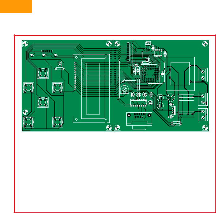
That means we can’t provide installation instructions along the line of ‘first loosen the four screws on the bottom’, etc. In this regard, you’ll have to rely on your own talent for improvisation. That also applies to the printed circuit board. Of course, you can use our design (Figure 3), but it probably won’t fit in oven models (and it’s anyway rather large; its full-size artwork files can be downloaded free of charge from our website). That means you will most likely have to design your own circuit board to fit in your oven. We assume that anyone who wants to solder components in BGA packages and the like is also capable of designing a circuit board for the controller circuit. In any case, our board design can serve as a starting point.
As regards safety, this circuit operates at 230 VAC, which means it can pose a fatal hazard if it is built or used improperly. As already mentioned, the mains voltage must be fused before it enters the circuit, and the fuse must be selected based on the maximum rated power of the heating elements. A separate thermal cutout is also essential.
Operation
We’ve kept the user operation aspects of our controller quite simple. When the unit starts up, a welcome message appears on the LCD and the microcontroller performs various checks. For instance, a warning message will be displayed if the EEPROM is missing, and a check is made to verify that a valid calibration value is stored in the EEPROM. If a valid calibration value is not found, the controller must first be calibrated. A message will be displayed to indicate that automatic calibration can be started by pressing ENTER.
If everything goes properly, the main menu will be displayed after calibration is finished. In the main menu, you can use the ↑ and ↓ buttons to select START, EDIT, LOG or CALIBRATE. Press the ENTER button to start the selected function.
Calibration
The CALIBRATE function performs a fully automatic measurement of the most important characteristic of the oven: its overshoot (see the ‘About the controller’ inset). Before you start a calibration, make sure the oven door is tightly closed and nothing is inside the oven. The controller will heat the oven
Figure 3. Our prototype circuit board isn’t likely to win a prize for pretty design.
The true-size artwork (pdf) files are available free of charge from our website.
|
250 |
|
|
dwell |
|
|
|
reflow |
|
|
pre-heat |
soak |
cool-down |
|
|
200 |
|
|
|
[°C] |
|
|
|
|
temperature |
150 |
|
|
|
|
|
|
|
|
|
100 |
|
|
|
|
|
measured temperature |
|
|
|
|
desired temperature |
|
|
|
50 |
|
|
|
|
0 |
|
|
|
|
|
time |
|
050319 - 13 |
|
|
|
|
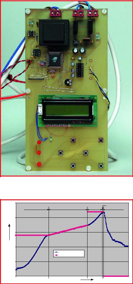
Figure 4. The actual temperature curve (blue) and the desired temperature (red).
We added extra rock-wool insulation to the oven to increase its heating rate.
1/2006 - elektor electronics |
33 |
HANDS-ON DIY REFLOW OVEN
Thermocouples
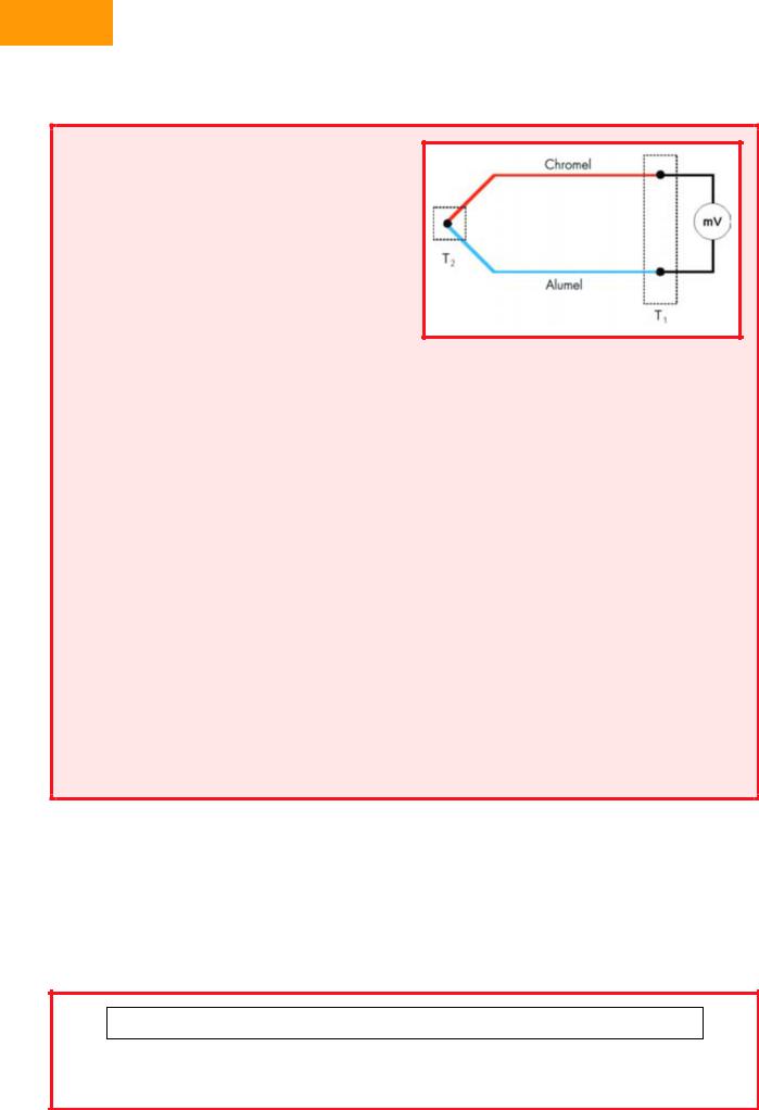
A thermocouple is a sensor that generates an electrical potential related to the temperature. The operating principle of the sensor is base on the fact that any electrical junction between two different metals generates an electrical potential that depends on the temperature and the metals that are used. The principle applies equally well if three metals are used. In that case, there are two junctions in series, and the net potential results from the series addition of the two individual potentials. For example, if a copper–iron junction is in series with an iron–tin junction, the net potential is the same as for a copper– tin junction. However, that is only true if both junctions are at the same temperature.
With a ‘K-type’ thermocouple, which is what we used for this design, the metals forming the thermocouple are always Chromel (on the positive side) and Alumel (on the negative side). The voltage generated by this combination is approximately 4 mV / 100 °C. K-type thermocouples can withstand temperatures of 1000 °C or more without suffering any damage.
However, thermocouples also have an inherent drawback: connecting a thermocouple to a circuit inevitably creates additional junctions between different metals, which naturally generate their own thermal potentials. Strictly speaking, the potential at the output of a thermocouple is not a function of the absolute temperature at the measurement point, but instead a function of the difference between the temperature at the measurement point (the hot junction) and the temperature at the connection point (the cold junction).
In our circuit, the cold junction is located on the circuit board. If we measure the temperature of the circuit board, we can calculate the actual temperature at the measurement point from the voltage generated by the thermocouple and the temperature of the circuit board.
Fortunately, the MAX6675 IC used in the circuit automatically looks after all that for us. It measures the voltage from the thermocouple and converts it into a temperature difference between the hot junction and the cold junction. We assume that the temperature inside the IC is essentially the same as the temperature of the circuit board (the cold junction). If we add the chip temperature to the computed difference
between the temperatures of the hot junction and the cold junction, we obtain the temperature of the hot junction, which it the temperature at the point we want to measure.
This assumption regarding the cold-junction temperature is why it’s important for the thermocouple leads (which are made from Chromel and Alumel) to be soldered to the circuit board as close to the IC as possible. That also means that if you have to extend the thermocouple leads, you must use Chromel wire for the positive side and Alumel wire for the negative side. If you use normal copper wire, the junctions with the copper wire will form additional measurement points. That will create a measurement error if the temperatures of those junctions are not the same as the temperature of the circuit board. It’s thus best to buy a thermocouple with sufficiently long leads.
It shouldn’t be necessary to say this, but we’ll say it anyhow for good measure: make sure your thermocouple is made from Chromel and Alumel. In other words, ensure that it is a K-type thermocouple. Other types of thermocouples generate different potentials, which will result in incorrect measurements.
In case of doubt, you can easily check the measurements. If you put the thermocouple in ice water, the circuit should indicate a temperature of approximately 0 °C. If you put the thermocouple in boiling water, the circuit should indicate a temperature of approximately 100 °C. If you have any doubt, we definitely recommend making this test.
to 100 °C and switch off the heating elements. The temperature inside the oven will continue rising for a short while until it reaches some maximum value. When the temperature has just about stopped rising, the microcontroller calculates the associated overshoot value. That value is stored in the
EEPROM, so the calibration routine does not have to be repeated every time the oven is used.
Edit
Different types of solder paste may have different rated soldering temper-
atures. The melting temperature and the temperature needed to activate the flux depend on the composition of the solder paste. You also have to consult the data sheets of the components you use to determine the requirements for the temperature profile (in other words, the settings). You can deviate from the
STAGE, TEMPERATURE, DESIRED TEMPERATURE, HEATER 1, HEATER 2
STAGE : |
0 |
= COOL |
1 = PREHEAT |
2 = SOAK |
3 = REFLOW |
4 = DWELL |
5 = COOL |
HEATING : |
0 |
= OFF |
50 = ON |
|
|
|
|
Figure 5. The format of the data sent to the PC. ‘Stage’ indicates the progress of the process, ‘Temperature’ indicates the current temperature in the oven, ‘Desired temperature’ is self-explanatory, and ‘Heater 1’ and ‘Heater 2’ indicate whether the heating elements in question are switched on.
34 |
elektor electronics - 1/2006 |

manufacturer’s requirements in actual practice, but if you do, there’s no guarantee that the components will still be intact after soldering.
The temperature profile generated with the settings we used for our controller is shown in Figure 4. The values shown in the figure are guidelines; we have achieved good results with them on our lab.
Log
The LOG menu lets you enable or disable the built-in temperature logging function. The logging function is disabled by default when the unit is switched on. That avoids rewriting the contents of the EEPROM any more often than necessary, which helps prolong the useful life of the EEPROM.
You can enable logging with the ↑ button and disable it with the ↓ button. If you press the → button, the content of the temperature log for the most recently logged soldering cycle will be transmitted via the serial port. The settings used for the serial port are 4800, 8, N and 1 for the baud rate, number of data bits, parity, and number of stop bits.
The stored values are separated by [RETURN] codes. You can use HyperTerminal or any other suitable communications program to store the data stream in a file. It’s a good idea to assign the extension ‘.csv’ to the file name. That makes it possible to open the file using a spreadsheet program. In a program such as Excel, you can then generate a chart from the data to show the actual temperature plot (temperature profile).
Press [ESC] to return to the main menu.
Start
The START function does exactly what it says: it starts the soldering process. The display provides a convenient indication of the progress of the process. If anything goes wrong, you can always stop the soldering process by pressing the [ESC] button.
Another way to modify the process is to use the ↑ and ↓ buttons. You can use these buttons to increase or decrease the desired temperature while the oven is operating.
Another handy feature is that the most significant data is transmitted via the serial port during the soldering process. The same settings are used here as for reading out the EEPROM, namely 4800, 8, N and 1 for the baud
Figure 6. The four stages in PCB form: without solder paste, with solder paste, components not yet soldered, and finished circuit board.
rate, number of data bits, parity, and number of stop bits.
The format of this data is shown in Figure 5. The data can also be stored on hard disk using HyperTerminal and then processed in a spreadsheet program. The temperature profile shown in Figure 4 was generated in this manner.
Practical experience
We’ve used our SMD oven successfully several times already for soldering prototypes. However, each time we had to open the door at the end of the soldering process to reduce the cool-down time.
Most inexpensive ovens don’t have a fan to help cool down the oven. There’s also no provision in our circuit for a fan. For people who only want to solder the
occasional circuit board, it shouldn’t cause a big problem if someone has to keep an eye on the oven and open the door when the process is finished.
It’s a good idea to make sure the solder paste you buy is suitable for use at the lowest possible temperature. New solder paste compounds comply with the RoHS requirements, which among other things means they do not contain any lead. That makes the melting point of the solder somewhat higher. The situation in this area is currently rather dynamic, so you should remain on the lookout for solder paste compounds with relatively low melting points.
And while we’re on the subject of solder paste, it’s recommended to store solder paste in a refrigerator to prolong its useful life.
(050319-1)
This circuit operates at 230 VAC, which means it can pose a fatal hazard if it is built or used improperly.
1/2006 - elektor electronics |
35 |
HANDS-ON MICROCONTROLLERS
The R8C Fam
16-bit power for the masses
Gunther Ewald and Burkhard Kainka
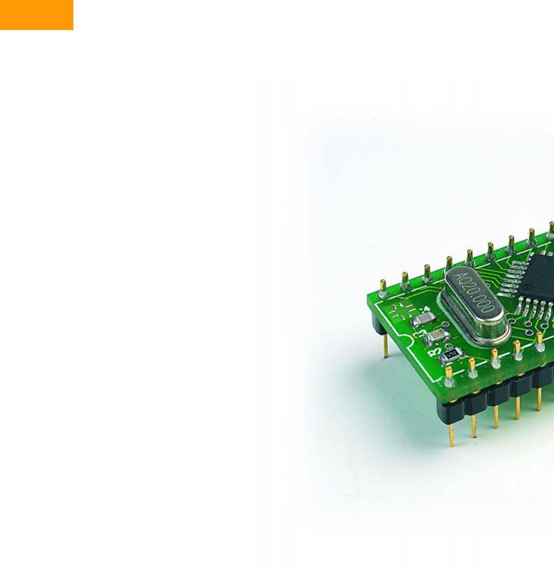
Starting next February, we will be offering a small but elegant R8C microcontroller board in cooperation with Glyn, along with a wealth of software, at a simply unbeatable price. This little board is fully ready to use. Here we take the opportunity to first introduce the microcontroller.
Microcontrollers from the Japanese company Renesas have quietly captured a position in the European market. They are typically used in applications such as automobile sensor systems, fire detectors, door openers, heating system controllers, measuring equipment, and stereo systems.
We’ve reason to believe practically all readers of Elektor Electronics are familiar with the 8051 and AVR microcontroller families, but quite a few of them have never heard of the M16C and the R8C. That’s a pity, because the small R8C microcontroller is particularly suitable for applications that challenge the capabilities of the more familiar devices. Besides that, it’s actually quite easy to use. The internal flash memory can be programmed via the serial port, so no special programming device is necessary. In many cases, you can manage without a clock crystal in the ultimate application. And finally, all the software you need to develop your own applications is freely available.
The origins
In 1996, Mitsubishi Electric started replacing its successful MELPS7700 microcontroller with its successor, the M16C/60. The new device had the same peripherals but a significantly faster processor, and with 100 pins it outscored its predecessor by 20 pins. The driving forces
at that time were the Japanese manufacturers of ink-jet printers and photocopiers.
Thanks to its large complement of timers and very low current consumption, the new microcontroller quickly found its way into industrial equipment manufactured by European companies. The M16C became even more popular in late 1998 with the introduction of DINOR flash memory, which does not need a special programming voltage. A data retention time of 10 years was guaranteed.
The standard M16C/62 has been updated three times over the years. Starting with the M16C/62, it evolved into the M16C/62A and then into the current M16C/62P. Each time the internal dimensions were reduced, a few new features were added, and the device became faster and more modern, with reduced current consumption and a lower cost. However, it always remained pinand function-compatible.
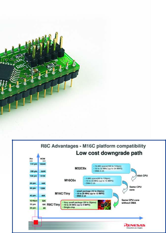
Derivative devices in smaller and larger packages started appearing in 1999, along with the R8C family and the M32C, which rounded out the top end of the family. These microcontrollers were initially manufactured by Mitsubishi Electric, but in 2003 Hitachi and Mitsubishi Electric merged to form a new company christened ‘Renesas’. All of the family members and their data sheets can be found via the home page www.m16c.de.
As can be seen from the summary in Figure 1, once
36 |
elektor electronics - 1/2006 |
ily |
|
|
In cooperation with Glyn (www.glyn.de), the leading distributor of |
||
|
||
|
Renesas microcontrollers, starting in February 2006 Elektor |
|
|
Electronics will be offering a fully assembled R8C/13 circuit board |
|
|
and a comprehensive software CD, all at a special price. |
|
|
|
|
|
you’ve mastered the R8C you have a lot of opportunities |
|
|
for further growth. The transition to the next higher deriv- |
|
|
ative device is fully seamless. Besides the fact that you |
|
|
can continue using the same compiler, all existing appli- |
|
|
cations can easily be used and extended with the new |
|
|
device. Even moving to a data width of 32 bits doesn’t |
|
|
cause any headaches. All in all, that means it’s worth tak- |
|
|
ing a closer look at the smallest member of the powerful |
|
|
Renesas family. |
|
|
The family |
|
|
The R8C was developed in 2003 as a pin-compatible, |
|
|
cost-optimised version of the M16C/10. The entire Mit- |
|
|
subishi series, including the M16C/10, has an internal |
|
|
16-bit data path to the flash memory and SRAM. |
|
|
In order to save silicon area, Renesas simply reduced the |
|
|
bus width to 8 bits and integrated the new ‘Hyper New |
|
|
Dinor’(HND) flash memory. The addressable internal |
|
|
memory space was also reduced from 1 MB to 64 KB. In |
|
|
addition, the new 4-wire debug interface was added to |
|
|
the R8C. That made the R8C itself and application pro- |
|
|
gram development very economical. |
|
|
With its smaller package size (20 pins instead of 32), |
|
|
the R8C microcontroller is also suitable for applications |
|
|
such as model building, instrumentation sensors and |
|
|
data loggers. |
|
|
We’ll be devoting our attention to the R8C (or more |
Figure 1.
The R8C and the other members of its family make upgrading easy.
1/2006 - elektor electronics |
37 |
HANDS-ON MICROCONTROLLERS
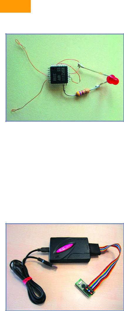
Figure 2. A LED blinker using the R8C/13 – no crystal necessary!
specifically the R8C/13) in the coming issues of Elektor Electronics. We have planned articles on how to use the software and some typical application examples. Naturally, a user competition also forms part of the picture. Here we’d like to whet your appetite a bit by describing the principal features of this small but elegant microcontroller.
The core
The CPU achieves a processing performance of 8 MIPS at a 20-MHz clock frequency and boasts 89 native instructions. Of that number, 20 are single-cycle instructions, and three quarters of the instructions execute in five clock cycles on average. Mathematical operations, such
Figure 3. The model E8 hardware debugger (optionally available) has a true real-time mode.
as a 16-bit by 16-bit multiplication, are completed in 250 ns, and division of a 32-bit quotient with a 16-bit dividend takes 1248 µs. The instruction set includes an RMPA instruction (calculate sum of products), which can be used to compute digital filter algorithms.
The instruction set has special space-saving instructions that allow short data words (with a length of 1, 2, 4 or 8 bits) to be stored in one, two or three bytes along with the instruction opcode. The same capability is also available for addresses. The Compare function has been extended to enable MOV instructions to load data depending on flag states without requiring a prior comparison.
The peripherals
The R8C/13 has three 8-bit timers, one 16-bit timer, a watchdog timer, a very fast 10-bit A/D converter with twelve inputs and a conversion time of 3.3 µs, two UARTs (one of which can also be used synchronously), flash program memory, flash data memory in the form of a virtual EEPROM, SRAM, eight I/O lines with a rated current of 20 mA (for directly driving devices such as LEDs), an undervoltage detector, two integrated oscillators (calibratable 125-kHz and 8-MHz ring oscillators), and a crystal oscillator. The reset peripheral is also integrated using a 5-bit counter.
As with other Renesas microcontrollers, the current consumption is very low. It is 7.9 mA at 5 V and 16 MHz, dropping to 4 mA at 5 V for operation using the 8-MHz ring oscillator or 470 µA at 5 V for operation using the 124-kHz ring oscillator. In Stop mode the current consumption is only 0.7 µA.
A particularly attractive feature for model builders is the IC’s ability to boot using the low-speed oscillator. As can be seen from Figure 2, all you need to implement a minimal application (such as a LED blinker) is a programmed R8C/13 and a resistor.
The debug interface
The R8C family has an integrated debug interface with asynchronous and synchronous serial interfaces for easy, inexpensive debugging. The asynchronous mode is especially easy to use, because all you have to add is an RS232 level converter. For debugging you will need the KD30 debugger program, which first flashes a monitor program into the R8C and then starts it automatically. The debug interface is also suitable for downloading a fully developed program in the flash ROM of the microcontroller. You can use the Flashstart or FDT program for this purpose.
These programs, as well as all other software mentioned here, are available free of charge from www.renesas.com or www.m16c.de. Naturally, the programs are also located on the software CD-ROM available from Readers Services.
The tools
Renesas supports developing small, medium-sized and large projects using corresponding software. In that regard, a distinction must be made between three levels, which differ in cost, scope and capability. At the first level, the potential user can manage entirely without purchased software. There is even a GNU C compiler available now for the M16C family.
38 |
elektor electronics - 1/2006 |
Preliminary exercises
The following programs can be used to check whether a particular task can be handled using the R8C. Program installation should not present any problems for experienced microcontroller users as long as they follow the instructions. Detailed instructions will be provided in the February 2006 issue. Note that these programs must be installed in the proper sequence.
1 The Renesas KD30 monitor and debugger program is part of the HEW program, but it can also be used separately for debugging. The KD30 and HEW programs
are compatible with the NC20 compiler, the GNU C compiler, and the IAR or Tasking C compilers. The software can be found under www.renesas.com _ Global Site _ Software and Tools _ Download.
Confirm the licence conditions with ‘Agree’ and then click on ‘Evaluation Software’. Next, click on ‘Monitor Debuggers and Others’ under ‘Upgrades’ and then select ‘KD30 UART’. After that, the full set of programs (with a size of 5.6 MB) can be downloaded.
2 The free version of the Renesas NC30 C compiler, including HEW, can generate up to 64 KB of code, which can be debugged using the KD30 or HEW pro-
gram. You can download the software from www.renesas.com _ Global Site _ Software and Tools _ Download.
Here again, confirm the licence conditions with ‘Agree’ and then click on ‘Evaluation Software’. You will find ‘M3TNC30WA’ under ‘C/C++ Compilers and Assemblers’, and
once again you have to confirm by clicking on ‘Agree’. The size of the file is approximately 65 MB.
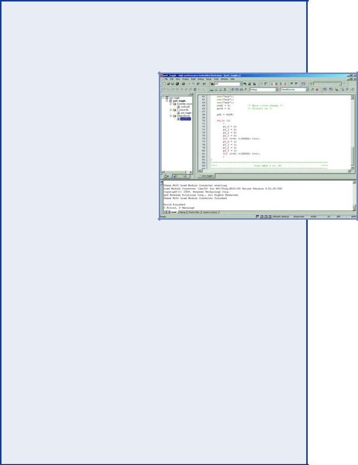
The HEW (High-Performance Embedded Workshop) program is a user interface for generating, debugging and flashing projects. The debugger is compatible with the NC30 compiler and the GNU C compiler.
3 The ‘Debugger Package’ is the software for linking KD30 into the HEW, and it is also available at www.renesas.com _ Global Site _ Software and Tools _ Download. Here you should confirm with ‘Agree’ as usual and then click on ‘Upgrades’.
Under ‘In-circuit Emulators and Compact Emulators’, you can then select ‘PC7501 for M16C Family’ and download the ‘Debugger Package’, which has a size of approximately 81 MB.
4The KPIT GNU C compiler does not have any operational restrictions, and the code it generates can also be debugged using the KD30 or HEW program. The compiler is available at www.kpitgnutools.com. You can download the software (size: 27 MB) after completing a registration form.
5The Renesas FDT (Flash Development Toolkit) can program the flash memories of near all Renesas MCUs. It is available at www.renesas.com _ Global Site _ Software and Tools _ Download. After clicking on ‘Agree’, you can click on ‘Evaluation Software’, select ‘Flash Development Toolkit’ under ‘Flash and PROM Programming’, and download the software (size:
approximately 27 MB).
6 Flashstart is a well-known flash program dating from the days of Mitsubishi Electric. It can flash all MCUs in the R8C/M16C/M32C family. The program is located at www.renesas.com _ Global Site _ MPU&MCU _ R8C/Tiny (upper table). There you have to select ‘Software and Tools’, go to ‘Flash and PROM Programming’, click on the ‘M3A-0806’
product, go to ‘Software Update’ on the left, and confirm by clicking on ‘Agree’. Here you can download the source file (which you don’t need) and the .exe file (size: 334 kB).
7 Header files and assembler ‘include’ files are located at www.renesas.com _ Global Site _ Software and Tools _ Download.
After clicking on ‘Agree’, you can select ‘M16C Family’ under ‘Sample Codes’ and download the desired files.
1/2006 - elektor electronics |
39 |
HANDS-ON MICROCONTROLLERS
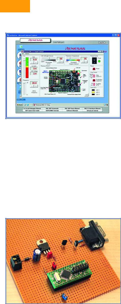
Figure 4. You can actively program an R8C via the Internet.
Level 1: On the hardware side, the simplest option only requires a level converter for the RS232 interface, as previously mentioned, and a serial interface cable. To that you can add the free Renesas NC30 compiler with its integrated development environment (HEW).
Although the compiler is restricted to 64 KB, that does not impose any restriction on projects using the R8C, since it can anyhow only address a maximum of 64 KB. Besides C projects, it’s also possible to develop assemblylanguage programs. The debug output format is
IEEE 695.
The HEW program or the KD30 program (also free of charge) can be used for debugging. Code generated by
Figure 5. And experimental prototype circuit using the R8C/13 board. This circuit will be presented in the February 2006 issue.
the GNU C compiler can also be debugged using this tool. All you have to do is to change the debug format to IAR/ELF Dwarf2. You can use Flashstart or FDT to flash the finished application into the microcontroller.
Level 2: If you want to perform debugging using a synchronous serial interface, independently of the crystal frequency and without using a monitor, you need Renesas’s smallest hardware debugger, the model E8 (Figure 3).
For the duration of this series of articles, it can be obtained from Glyn GmbH & Co. KG at a special price of €110 (ex VAT) instead of the regular price of €150. The E8 can generate breakpoints at data location as well as addresses, and it supports genuine real-time program execution and extended trace levels. The PCB pads for connecting this tool are already present in the free area of the circuit board described in the December issue. All you have to add is a few header pins.
The integrated development environment (HEW) is also used for debugging at this level, because it is the only one that supports the E8. Here again, either the NC20 compiler or the GNU C compiler can be used. Flashstart or FDT can then be used to flash the finished application into the microcontroller.
Level 3: For professional software development, R8C software can also be debugged using the Renesas PCC7501 real-time emulator, which naturally comes at a higher price. The PC7501 is connected to an emulation probe and provides countless features for searching for errors. It can measure program execution times and record the individual steps executed before a bug. It can also record digital signals from the application circuit ‘on the side’ with a resolution of 1 µs.
The outlook
If your curiosity has been aroused by now, you can already start doing a few ‘preliminary exercises’ with the R8C. The www.renesasinteractive.com website is a good resource for this. There you can even program a genuine starter kit via the Internet (see Figure 4), and you can naturally learn more about the features of the R8C. The only software you need to have installed on your computer for these functions is a web browser. The NC30, NEW and KD30 programs run entirely on the remotely controlled computer.
Besides this, you can also use your own computer to check whether specific tasks can be handled using this microcontroller. However, that does require installing a few programs before you start (see inset). It must be admitted that the necessary software takes up a certain amount of space and requires some familiarisation. Naturally, all of the programs will be provided on the software CD-ROM available from Readers Services, and detailed installation instructions will also be provided with the programs.
All of that will be topped off with simple projects to make your first steps with the R8C/13 even easier. Figure 5 shows an experimental prototype of a circuit planned for the February 2006 issue. It doesn’t require much more than a voltage regulator and a pair of transistors for the serial interface!
(050179-1)
40 |
elektor electronics - 1/2006 |