

AutoCAD & AutoCAD LT All-In-One Desk Reference For Dummies (2006)
.pdf732 Parts of a VBA Project
Declaring variables
A variable is a way to store data in memory for use later, to hold the value of an argument that is passed into a procedure, or to capture the returning value of a function. To use a variable, you should first use the Dim statement to dimension (or declare) the variable as a specific data type. Declaring the variable as a specific type helps the editor to check the data integrity of the code when it is being executed and debugged.
Variables can be defined locally within a given procedure or module and globally at a module level. For most data types, you only need to dimension the variable and assign the value that you want stored with it. Some examples of variables are
Dim strValue as String
Dim vVar
Data types
Data types are used to describe what type of data a variable holds; only a single data type can be assigned to a variable at one time. By default, when a variable is not declared with the Dim statement, or when it is defined with the statement but no data type, it is declared as a variant. Variants are often used to capture return values and as arguments for a procedure, in some cases based on the type of information that is being passed in.
Table 4-1 shows some of the commonly used data types in VBA.
Table 4-1 |
Common Data Types |
|
Data Type |
Brief Description |
Examples |
|
|
|
Boolean |
A true or false value. |
True |
|
|
|
Integer |
Any whole number without decimal places. |
10 |
|
–32,768 to 32,767 |
|
|
|
|
Double |
Any large number with decimal places and is accurate |
1.0, 0.23451, .5 |
|
up to 16 digits. |
|
|
1.80 x 10308 to –4.94 x 10-324 for neg.; 4.94 x 10–324 to |
|
|
1.80 x 10308 for positive values |
|
|
|
|
String |
Any number of alphanumeric characters enclosed in |
“Hello” |
|
double quotes. |
|
|
Range is from 0 to approximately 2 billion characters. |
|
|
|
|
Object |
A valid COM object. |
objLine |
|
|
|
Variant |
Any numeric range up to a double, a text string, or |
183.59 |
|
COM object. |
|
|
|
|

Parts of a VBA Project 733
Assigning a value to a variable
The equal sign (=) is used for value assignment to a variable. The value on the right is assigned to the variable on the left. If an object is being returned to be stored in a variable, the Set statement must be used in conjunction with the equal (=) sign. Some examples of value assignment are
‘String value assignment Dim strValue as String strValue = “Hello out there”
‘Object value assignment Dim acObjLine as AcadLine
Dim dPT1(0 to 2) as Double, dPT2(0 to 2) as Double
dPT1(0) = 0: dPT1(1) = 0: dPT1(2) = 0 dPT2(0) = 5: dPT2(1) = 5: dPT2(2) = 0
Set acObjLine = ThisDrawing.ModelSpace.AddLine(dPT1, dPT2)
The basics of working with objects
You may encounter objects throughout the use of the AutoCAD Object Library and when working with UserForms and controls. Objects come in two different distinct types: objects and collections.
Objects exist as individuals and as part of a group containing many objects of the same kind. The group of objects is referred to as a collection. The first object that you encountered when you opened the Visual Basic Editor is ThisDrawing, which is an example of an individual object. ThisDrawing represents an object of the data type AcadDocument. ThisDrawing is an object that represents the current drawing and is part of a collection that contains all open drawings in the application called AcadDocuments, which is part of the AcadApplication object.
Now that you are familiar with one type of object, you must know how to interact with it. After you have a reference to an object, you use a dot to access its properties or methods. At times, you are accessing an object below the current object that you are referencing. The following syntax represents how to access the properties and methods of an individual object and not one that is part of a collection. The syntax shows a space before and after the dot for readability, but there are no spaces on either side of the dot when writing the line in a code window:
Object . <Object or Property or Method>
ThisDrawing.FullName
ThisDrawing.ModelSpace.AddLine dPT1, dPT2
Book X
Chapter 4
Basic VisualAutoCAD
for

734 Introducing the AutoCAD Object Model
If you need to access an object that is part of a collection, you need to do a little more work. Objects contained in a collection have to be accessed in a slightly different way. Objects contained in a collection are indexed and are accessible by using their unique names or a number in most cases. The index is the order in which the items are added to the collection and is similar to a street address for a house. All houses have unique street numbers, so they can get their mail; indexes for collections work the same way. Most collections begin with an index of 0; however, some start with an index of 1. The collection works the same whether the first item of the collection starts at 0 or 1. (Really it’s what the programmer felt like using that day for the first item’s index.) Here are a few examples of how to access a layer from the Layers collection in a drawing.
ThisDrawing.ActiveLayer = ThisDrawing.Layers(“0”)
ThisDrawing.ActiveLayer = ThisDrawing.Layers(1)
As mentioned earlier, the Set statement must be used to store a reference to the object in a variable:
Dim objLayer As AcadLayer
Set objLayer = ThisDrawing.Layers(“0”)
Adding comments
A comment is a line or series of lines in a code module that do not get executed. A comment can be used to identify what is taking place in a procedure or may consist of a general note at the top of the module that includes general revision and author information. An apostrophe (‘) or single quote mark is placed at the front of a text string to designate it as a comment. By default, a comment appears in the color green within the Visual Basic Editor. An example comment is
‘ Close out application
Introducing the AutoCAD Object Model
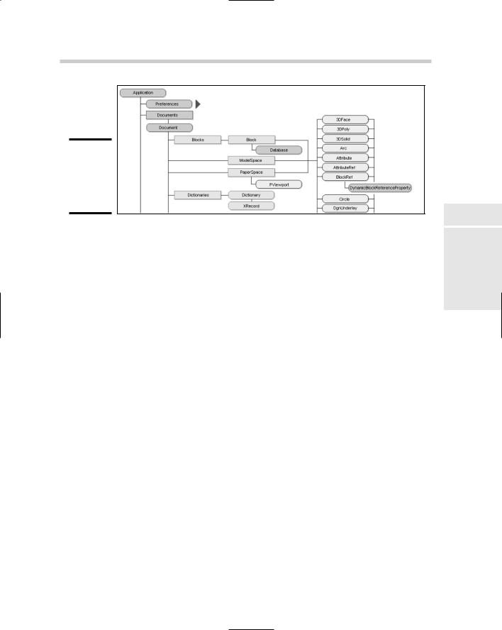
The AutoCAD Object Model is the organizational structure that is used to navigate the Object Library. The AutoCAD Object Model (see Figure 4-11) is very large; only a small portion is shown here.
Introducing the AutoCAD Object Model 735
Figure 4-11:
A view of the AutoCAD Object Model.
At the top of the AutoCAD Object Model is the Application; below that are the Preferences and Documents collections. You can identify that they are collections because their names end with s. Just below the Documents collection are the Document objects; this is the level that ThisDrawing represents in the object model. To give you an idea of what each Document is made up of, the following properties and methods, and many others, are part of the Document object:
ActiveLayer: Property to set and return the current layer.
FullName: Property to return the drawing’s name with path.
Blocks: Method returns a reference to the AcadBlocks collection.
SaveAs: Method used to save the drawing with a different name or location.
These steps show you how to open the AutoCAD Object Model Map in the AutoCAD Online Help system:
1.From the Help menu in the AutoCAD, choose Additional Resources
Developer.
2.Click the Contents tab and expand ActiveX and VBA Reference.
3.Select Object Model just below ActiveX and VBA Reference on the Contents tab.
Create a basic VBA project
Book X
Chapter 4
Basic VisualAutoCAD
for
If you’ve come this far, you should be ready to build a small VBA project to add a line in the current drawing.

736 Introducing the AutoCAD Object Model
The following procedures describe how to create a new empty VBA project:
1.From the Tools menu, choose Macro VBA Manager.
The VBA Manager dialog box should now be displayed.
2.Click the New button on the right side of the dialog box.
If no projects were previously loaded, a new project named ACADProject is added to the Projects list box with the location of Global1.
3.Select the new project in the Projects list box.
4.Click the Save As button on the right side of the dialog box.
The Save As dialog box is displayed, allowing you to specify a filename and location for the new VBA project.
5.Browse to the My Documents folder using the Save In drop-down list.
6.Enter FirstVBAProject in the File Name field of the Save As dialog box.
7.Click the Save button in the Save As dialog box.
The empty VBA project is saved to the My Documents folder. The location and filename that the project is saved to are reflected in the VBA Manager dialog box under the Location column.
Working with the new VBA project in the editor
Here is how to launch the Visual Basic Editor and work in the new project:
1.Select the new project in the Projects list box.
2.Click the Visual Basic Editor button on the bottom of the VBA Manager dialog box.
The Visual Basic Editor should be launched and be displayed on-screen. If it is not brought up on-screen, check the Windows taskbar to see whether it is minimized.
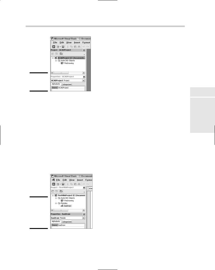
3.In the Project Explorer, select the top node ACADProject, which represents the project.
In the Properties window (see Figure 4-12), the properties for the project should be listed. A project has one property that can be modified from the Properties window, and that is Name.
4.Highlight the current value of ACADProject in the Name field in the Properties Window and enter FirstVBAProject.
This changes the name that appears in the VBA Manager dialog box and the Macros dialog box. Using a unique name lets you distinguish the project from other loaded projects.
Introducing the AutoCAD Object Model 737
Figure 4-12:
Name that property.
5.Right-click in the Project Explorer and choose Insert Module.
A new standard code module named Module1 is added to the project. You should also notice that a new folder named Modules is automatically created under the project. All standard code modules that are imported or created in the project are added to this folder.
6.Select Module1 from the Project Explorer and change the Name property for Module1 to basDraw through the Properties window.
A project can have more than one module, so it is a good idea to give each module a unique name. If you wanted to use the module in a different project, you would want to make sure it was imported with a unique name; otherwise, it can’t be imported into a project if that name is already in use. The project and standard code module should both be renamed now (see Figure 4-13).
Figure 4-13:
Visual Basic Editor with new project and code module.
Book X
Chapter 4
Basic VisualAutoCAD
for
738 Introducing the AutoCAD Object Model
Going further with AutoCAD and VBA
In addition to the information we cover in this chapter, you should explore the AutoCAD Object Model and take a look at the different objects and collections that are in the AutoCAD Object Library through the Object Browser in the Visual Basic Editor. AutoCAD also ships with a variety of samples that can be found in
the folder C:\Program Files\AutoCAD 2006\ Sample\VBA by default. Don’t forget about the invaluable tool the Internet can be; it is a great tool for finding tutorials that demonstrate how to use VBA for AutoCAD as well as many other host applications.
Adding a new procedure to a code module
These steps describe how to create a new procedure in a code module:
1.Click in the Code window for the new code module.
A code window should have opened up automatically when the new code module was added. If not, double-click on basDraw in the Project Explorer for the project. Clicking in the code window sets the focus to the code window or at the desired location within the code window.
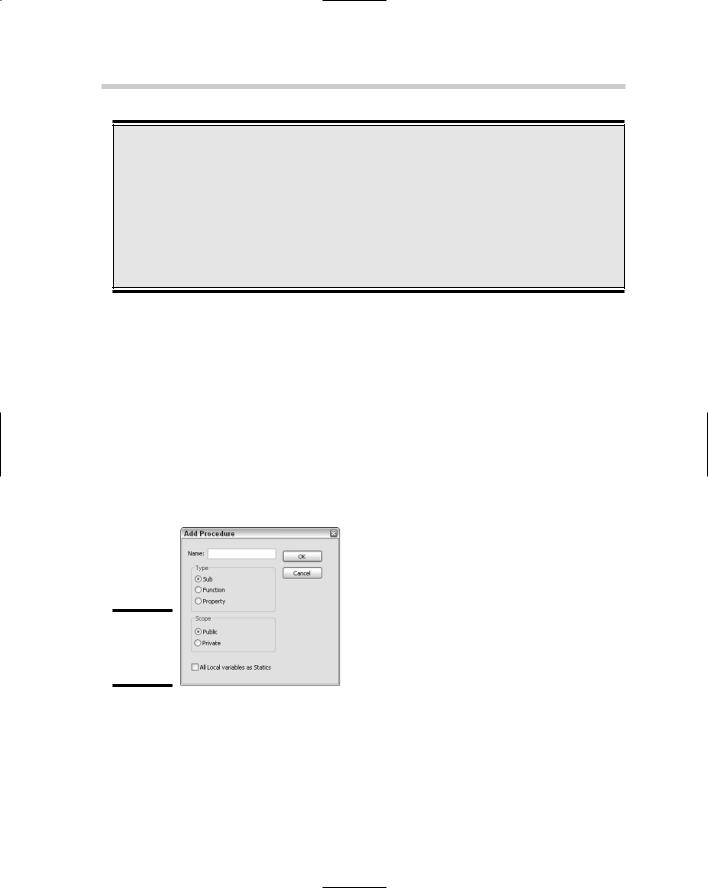
2.From the Insert menu in the Visual Basic Editor, choose Procedure.
This launches the Add Procedure dialog box (see Figure 4-14).
Figure 4-14:
The Add Procedure dialog box.
3.Enter DrawLine in the Name field.
The name entered is what will be used by the Macros dialog box and the -VBARUN command or will be used to call the subroutine from another location in the code.
4.Click Sub under the Type section.
Introducing the AutoCAD Object Model 739
The new procedure should be a subroutine because no return value is required.
5.Click Public under the Scope section.
The new procedure needs to be public so it can be accessed from the Macros dialog box and outside the code module it is defined in.
6.Click OK in the Add Procedures dialog box.
The new procedure is added to the code window and should look like this one:
Public Sub DrawLine()
End Sub
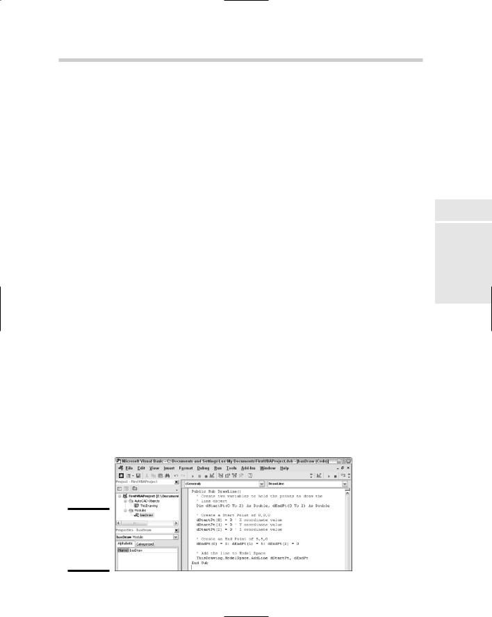
7.Add this code between the two lines of code that were added by the Add Procedures dialog box.
‘Create two variables to hold the points to draw the
‘line object
Dim dStartPt(0 To 2) As Double, dEndPt(0 To 2) As
Double
‘Create a Start Point of 0,0,0 dStartPt(0) = 0 ‘ X coordinate value dStartPt(1) = 0 ‘ Y coordinate value dStartPt(2) = 0 ‘ Z coordinate value
‘Create an End Point of 5,5,0
dEndPt(0) = 5: dEndPt(1) = 5: dEndPt(2) = 0
‘ Add the line to Model Space ThisDrawing.ModelSpace.AddLine dStartPt, dEndPt
8.Click Save on the Standard toolbar in the Visual Basic Editor.
This saves the changes that have been made to the VBA project up to this point. The DrawLine procedure has now been defined (see Figure 4-15) and is ready for use in AutoCAD.
Figure 4-15:
The completed DrawLine procedure.
Book X
Chapter 4
Basic VisualAutoCAD
for

740 Introducing the AutoCAD Object Model
Running the new procedure
These steps describe how to run the DrawLine procedure:
1.From the View menu in the Visual Basic Editor, choose AutoCAD or switch to AutoCAD by clicking the icon in the Windows taskbar.
2.From the Tools menu in AutoCAD, choose Macro Macros.
The Macros dialog box is launched; it should list only one macro, DrawLine.
3.Select the macro from the list box (if it is not already selected) and click the Run button located on the right side of the Macros dialog box.
4.From the View menu in AutoCAD, choose Zoom Extents.
The new line should be displayed in the center of the drawing window. If you listed the line by using the LIST command or the Properties Palette in AutoCAD, you should notice that the new line starts at 0,0,0 and
ends at 5,5,0, which are the values that were defined in the DrawLine procedure.

Index
Numbers and Symbols
! (exclamation point), using with AutoLISP expressions, 689
!c, using in pull-down item names, 619 & (ampersand), using in pull-down item
names, 618
&&(double ampersand), using in pulldown item names, 619
( (left parenthesis), using with AutoLISP expressions, 689
(* [number number ...]) syntax in AutoLISP, description and result of, 695
(_> error message in AutoLISP, description of, 708
(+ [number number ...]) syntax in AutoLISP, description and result of, 695
* (asterisk), using in macros, 612
. (dot in VBA projects, 733–734
. (period), using in macros, 612
/ (slash), using with VBA files, 671
[] (square brackets), meaning of, 121
\(backslash), using in macros, 612
\\ (double backslash)
using in macros, 612 using with VBA files, 671
^C, using in macros, 612
_ (underscore), using in macros, 612 (“_> error message in AutoLISP,
description of, 708
~ (tilde), using in pull-down items, 619 + function in DIESEL, effect of, 592
– function in DIESEL, effect of, 592
2D coordinate system, explanation of, 95
2D display commands DSVIEWER, 172 -PAN, 172
PAN, 172 REDRAW, 172 REDRAWALL, 172 REGEN, 172 REGENALL, 172 REGENAUTO, 172 VIEW, 172 VIEWRES, 172 ZOOM, 172–173
2D drafting
comparing in AutoCAD versions, 255, 271
switching between 3D drafting, 288 2D drawing commands
ARC, 118 ATTDEF, 118 BLOCK, 118 BOUNDARY, 118 CIRCLE, 118 DLINE, 118 DONUT, 118 ELLIPSE, 118 GRADIENT, 118 HATCH, 118 LINE, 118 MLINE, 118 MTEXT, 118 PLINE, 119 POINT, 119 POLYGON, 119 RAY, 119 RECTANG, 119 REGION, 119 REVCLOUD, 119 SKETCH, 119 SOLID, 119 SPLINE, 119 TABLE, 119 TRACE, 119 XLINE, 119