642 Creating Custom Patterns
Creating a hatch pattern
Follow the procedures below to create a new hatch pattern.
1.Choose Start [All] Programs Accessories Notepad.
Notepad is launched and a blank document is created.
2.From the menu bar in Notepad, choose File Open.
The Open dialog box is displayed.
3.In the Open dialog box, select All Files from the Save As Type dropdown list.
You should be able to see all file types, not just those with the extension
.TXT.
4.Browse to the location of Acad.PAT (Acadlt.PAT) and select the file, and then click Open.
Acad.PAT (or Acadlt.PAT) should be selected and opened into Notepad. By default, Acad.PAT can be found in the folder C:\Documents and Settings\<user name>\Application Data\Autodesk\AutoCAD 2007\ R17.0\enu\Support. If you are using AutoCAD LT, Acadlt.PAT can be found in the folder C:\Documents and Settings\<user name>\Application Data\Autodesk\AutoCAD LT 2007\R12\enu\Support.
5.Scroll all the way to the bottom of the hatch pattern file and position the cursor on the very last blank line in the file.
You should see a set of comments right above the last blank line that starts off with the comment ;; User Defined Hatch Patterns.
6.Enter the new hatch pattern header and descriptor lines.
The hatch pattern file should now include a header line for the hatch pattern and at least one descriptor line.
7.From the menu bar in Notepad, choose File Save.
The updated contents of the hatch pattern file are saved out to file.
A utility that is part of Express Tools allows you to use an image, block, external reference (Xref), or a wipeout object as a hatch pattern. This can be a great timesaver because you are using techniques that you already understand to create a hatch pattern. This utility is called Super Hatch and can be found on the menu bar under Express Draw Super Hatch.
If you don’t add your custom hatch patterns to one of the hatch pattern files that comes with AutoCAD, a hatch pattern file can only contain a single hatch pattern. The pattern name and the file name must be the same. If you create a file named glass.PAT, the pattern in the file must be named GLASS.
644 Working with Express Tools
Installing Express Tools
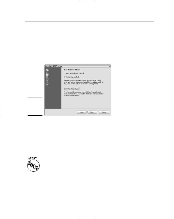
Express Tools can be installed during the installation process of AutoCAD. To install Express Tools, click the check box on the Install Optional Tools page (see Figure 4-4). If you installed AutoCAD without installing Express Tools, you can use the Control Panel in Windows to make changes to the installation using Add or Remove Programs. To access Add or Remove Programs, choose Start Control Panel Add or Remove Programs.
Figure 4-4:
Installing
Express
Tools.
After Express Tools has been installed, the Express menu should appear on the AutoCAD menu bar. If the Express menu is not displayed, type the command EXPRESSMENU or EXPRESSTOOLS at the command line.
Layer tools
The Layer tools give you capabilities ranging from selecting an object and displaying only the objects on that layer to being able to freeze a layer just by selecting it.
All of the Layer tools that were previously part of Express Tools have been integrated into AutoCAD 2007 and AutoCAD LT 2007 and can be located under the Layer Tools submenu of the Format menu.
Layer Manager: Layer Manager allows you to save and restore layer states. This functionality is very similar to the layer states in the Layer Properties Manager.
Layer Walk: Layer Walk allows you to dynamically step through all the layers in a drawing to see the objects placed on those layers, without forcing you to freeze or thaw or turn layers off and on.
646 Working with Express Tools
Explode Attributes to Text: Explode Attributes to Text allows you to explode a block, but instead of attribute definitions being created after the explosion, you are left with text objects in their place with the value that was in the attribute before the block was exploded.
Convert Shape to Block: Convert Shape to Block allows you to generate a block based on a shape definition.
Export Attribute Information: Export Attribute Information allows you to export attribute and block name information to a tab-delimited text file. This allows you to work with the information in a spreadsheet program.
Import Attribute Information: Import Attribute Information allows you to import previously exported attribute and block name information back into AutoCAD to sync up the values.
Convert Block to Xref: Convert Block to Xref allows you to replace a block with a specified Xref.
Replace Block with Another Block: Replace Block with Another Block allows you to replace a block with a specified block.
Text tools
The Text tools give you capabilities ranging from being able to create text along an arc to being able to change the case of several selected text objects at one time:
Text Fit: Text Fit allows you to stretch or shrink a text object by selecting a new or end point.
Text Mask: Text Mask allows you to place a mask object behind a text or mtext object with an offset value.
Unmask Text: Unmask Text allows you to remove a mask object from behind a text or mtext object.
Explode Text: Explode Text allows you to explode a text or mtext object into geometry that can be assigned thickness or an elevation.
Convert Text to Mtext: Convert Text to Mtext allows you to select text objects and create a single mtext object with the values from the selected text objects.
Arc-Aligned Text: Arc-Aligned Text allows you to create a text object that follows along an arc’s curve.
Rotate Text: Rotate Text allows you to change the orientation of a text, mtext, or attribute.

Working with Express Tools 647
Enclose Text with Object: Enclose Text with Object allows you to place a circle, slot, or rectangle around a text or mtext object.
Rotate Text: Rotate Text allows you to change the orientation of a text, mtext, or attribute.
Automatic Text Numbering: Automatic Text Numbering allows you to create a numbered list.
Change Text Case: Change Text Case allows you to change the case of selected text and mtext objects.
Layout tools
The Layout tools offer capabilities ranging from listing a viewports scale to synchronizing viewports:
Align Space: Align Space allows you to adjust a viewport based on points selected in model space and paper space.
Synchronize Viewports: Synchronize Viewports allows you to update a viewport’s zoom factor based on a specified viewport.
List Viewport Scale: List Viewport Scale allows you to obtain a viewport’s current scale factor.
Merge Layout: Merge Layout allows you to merge the objects in a layout into another layout or create a new layout based on the layouts being merged.
Dimension tools
The Dimension tools range from leader tools to tools that enable you to import and export dimension styles out of a drawing:
Leader Tools: The Leader Tools submenu contains commands that allow you to attach and detach leader lines to multiline text, tolerance, or block reference objects.
Dimstyle Export: Dimstyle Export allows you to export a specified dimension style out of a drawing to a text file.
Dimstyle Import: Dimstyle Import allows you to import a previously exported dimension style into a drawing.
Modify tools
Book IX
Chapter 4
Deeper DelvingCustomization
into
The Modify tools give you capabilities ranging from being able to perform multiple editing operations in a row to controlling display order by color:
648 |
Working with Express Tools |
Multiple Object Stretch: Multiple Object Stretch allows you to perform more than one crossing polygon before doing a stretch.
Move/Copy/Rotate: Move/Copy/Rotate allows you to perform move, copy, and rotate operations in a row on objects created during the command.
DrawOrder by Color: DrawOrder by Color allows you to control the draworder of objects in a drawing by the color they are assigned or by the color of the layer they are on.
Flatten Objects: Flatten Objects allows you to convert 3D objects into 2D objects.
Draw tools
The Draw tools range from inserting a breakline to a feature known as Super Hatch. Super Hatch allows you to use an image, block, external reference (Xref), or a wipeout object as a hatch pattern.
File tools
The File tools are used to help with the management of drawing and backup files. The utilities perform functions ranging from moving backups to a specified location to being able to save all open drawings in AutoCAD:
Move Backup Files: Move Backup Files allows you to specify where .BAK files should be placed after each save.
Save All Drawings: Save All Drawings allows you to save all open drawings without needing to switch to each one and saving each individually.
Quick Exit: Quick Exit allows you to exit all open drawings; you are prompted only for the ones that need to be saved. AutoCAD closes automatically after the command is done.
Revert to Original: Revert to Original allows you to close and reopen the current drawing.
Tools
The tools are a variety of different types of routines, ranging from editing the PGP file to creating custom linetypes:
Command Alias Editor: Command Alias Editor allows you to create new and modify existing command aliases in a PGP file.
System Variable Editor: System Variable Editor allows you to view and modify the values of system variables through a dialog box instead of at the command line.
650 Book IX: Customizing AutoCAD