

AutoCAD & AutoCAD LT All-In-One Desk Reference For Dummies (2006)
.pdf632 Working from a Script
Creating a script file
Because script files are plain text files, they can be created and edited with an application such as Notepad. Follow these procedures to create a new script file using Notepad:
1.Choose Start [All] Programs Accessories Notepad.
Notepad is launched and a blank document is created.
2.From the menu bar in Notepad, choose File Save As.
The Save As dialog box is displayed.
3.In the Save As dialog box, enter a name for the script file and make sure that .SCR is added to the filename in the File Name text field.
4.Browse to the location where you want to save the script file and click Save.
The script file is created in the specified location.
5.Enter the AutoCAD commands and options in Notepad that you want to execute when the script file is run.
Don’t forget that each command and option must be followed by a space, unless it is the last command or option on the line.
The text area of Notepad should contain the commands and options that you want to use in the script file.
6.From the menu bar in Notepad, choose File Save.
The contents of the Notepad document are saved to the script file.
Loading and running a script file
Use one of these methods to load and run a script file:
Tools menu: Choose Tools Run Script.
Keyboard input: Type SCRIPT at the command line and press Enter.
Command alias: Type SCR at the command line and press Enter.
These steps describe how to load and run a script file.
1.Use any of the three methods just listed to initiate the DIMLINEAR command.
The Select Script File dialog box is displayed.
It’s All in the Linetype 633
2.In the Select Script File dialog box, browse to the location where the script file is stored and select it. After the script file has been selected, click Open.
The selected script file is executed in AutoCAD.
You can also drag and drop a script file from Windows Explorer onto a drawing window to load and run the script in that drawing file.
Running a script file at startup
You can load and run a script file using one of the command line switches with a desktop shortcut. The /b switch is the command line switch that allows you to load and run a script at startup. This can be a great way to make sure that session-specific drafting settings are configured when AutoCAD is first
launched. Below is an example target path using the /b switch with a script file:
“C:\Program Files\AutoCAD 200X\acad.exe” /b Startup
The preceding example starts AutoCAD with a script file named Startup. The script file in this example must exist in the support search paths of AutoCAD. You can also specify the absolute path for the script file. See Chapter 1 in this minibook for more information about command line switches.
It’s All in the Linetype
Linetypes are repeating patterns used to help convey design ideas. Whether the drawings you create are architectural or mechanical, you most likely use more than one linetype in a drawing. Linetypes come in two different classifications: simple and complex. Complex linetypes are the same as simple linetypes with additional support for shapes and text strings.
Linetype files are plain text files that can be edited with a text editor and have the file extension .LIN. AutoCAD ships with two different linetype files, Acad.LIN (Acadlt.LIN) and Acadiso.LIN (Acadltiso.LIN). The Acad.LIN (Acadlt.LIN) file is used for imperial unit drawings, whereas Acadiso.LIN (Acadltiso.LIN) is used for metric-based drawings. A linetype pattern is defined using two different lines in the .LIN files.
The first line of a linetype file contains the Name and Description line; the second is the descriptor line that tells AutoCAD how to create the pattern. Linetype files also support the use of comments to help keep track of when changes were last made. Comments are defined with a semicolon, so AutoCAD ignores everything to the right of the semicolon. A section of the Acad.LIN file that ships with AutoCAD appears next:
Book IX
Chapter 4
Deeper DelvingCustomization
into
634 It’s All in the Linetype
;;Note: in order to ease migration of this file when upgrading
;;to a future version of AutoCAD, it is recommended that you add
;;your customizations to the User Defined Linetypes section at the
;;end of this file.
;;
*BORDER,Border __ __ . __ __ . __ __ . __ __ . __ __ . A,.5,-.25,.5,-.25,0,-.25
The system variable PSLTSCALE determines how linetype patterns appear when objects are displayed through a viewport. If the system variable PSLTSCALE is set to a value of 0, the linetype scale is determined by the system variable LTSCALE. However, if the system variable is set to a value of 1, linetype scaling is controlled by the scale factor of the viewport. See Book I, Chapter 5 for more information about linetype scale.
A utility that allows you to make a linetype out of geometry in a drawing is a part of Express Tools (which comes with AutoCAD, but not AutoCAD LT). This utility is great for getting started with creating your own linetypes. The utility can be found on the menu bar under Express Tools Make Linetype.
Simple linetypes
Simple linetypes are made up of only dashes, dots, and spaces and are the most commonly used linetypes. Examples of simple linetypes are CENTER ( ____ _ ____ _ ____ ) and HIDDENX2 ( ____ ____ ____ ).
Simple linetype structure
The best way to understand how a simple linetype is created is to take a look at one of the linetypes that comes with AutoCAD. One of the most commonly used linetypes is CENTER:
*CENTER,Center ____ _ ____ _ ____ _ ____ _ ____ _ ___
A,1.25,-.25,.25,-.25
Line 1 of the CENTER linetype’s definition:
*: Designates the start of the linetype.
CENTER,: The name of the linetype pattern. This name must be unique in the file; otherwise, AutoCAD uses only the first linetype with the name in the file and ignores all other instances. A comma is used to separate the name of the linetype from its description.

It’s All in the Linetype 635
____ _ ____: The description of the linetype pattern. The description is displayed in the Linetype Manager, Layer Properties Manager, Properties Palette, Properties toolbar, and other places in the application. The description is optional and can only be a maximum of 47 characters in length.
Line 2 of the CENTER linetype’s definition:
A,: The alignment flag is used to force AutoCAD to start and end the linetype with a dash instead of a space or dot. A comma is used to separate each data element.
1.25,: The length of a dash when LTSCALE is equal to 1. Dashes are represented by a positive value.
-.25,: The length of a space when LTSCALE is equal to 1. Spaces are represented by a negative value.
.25,: The length of a dash.
-.25,: The length of a space.
One of the other elements that is part of a simple linetype is a dot, which is presented by a value of 0 in a linetype pattern. You should place a gap on the left and right side of a dot so it stands out in the linetype pattern.
Creating a simple linetype
Because linetype files are plain text files, they can be created and edited with an application such as Notepad. Follow these steps to create a new simple linetype:
1.Choose Start [All] Programs Accessories Notepad.
Notepad is launched and a blank document is created.
2.From the menu bar in Notepad, choose File Open.
The Open dialog box is displayed.
3.In the Open dialog box, select All Files from the Save As Type dropdown list.
You should be able to see all file types and not just those with the extension .TXT.
4.Browse to the location of Acad.LIN (Acadlt.LIN) and select the file, and then click Open.
Acad.LIN (or Acadlt.LIN) should open into Notepad. By default, Acad.LIN can be found in the folder C:\Documents and Settings\<user name>\ Application Data\Autodesk\AutoCAD 2007\R17.0\enu\Support.
Book IX
Chapter 4
Deeper DelvingCustomization
into

636 It’s All in the Linetype
If you are using AutoCAD LT, Acadlt.LIN can be found in the folder C:\ Documents and Settings\<user name>\Application Data\Autodesk\ AutoCAD LT 2007\R12\enu\Support.
5.Scroll all the way to the bottom of the linetype file and position the cursor on the very last blank line in the file.
Above the last couple of blank lines, you should see a set of comments that begins with the comment ;; User Defined Linetypes.
6.Enter the new linetype pattern.
The linetype pattern file should now include the name and description for the linetype on one line and a descriptor on the next line.
7.From the menu bar in Notepad, choose File Save.
The updated contents of the linetype file are saved to file.
8.Load and use the linetype just as you would any other linetype that comes with AutoCAD.
The linetype works just like any of the linetypes that come with AutoCAD.
Using a custom linetype file
Adding custom linetypes to one of the linetype files that comes with AutoCAD is the easiest way to go, but at times, you might want to keep your custom linetypes in a separate file. Follow these procedures to load a linetype from a custom linetype file:
1.From the menu bar, choose Format Linetype.
The Linetype Manager dialog box is displayed.
2.In the Linetype Manager dialog box, click Load.
The Load or Reload Linetypes dialog box is displayed.
3.In the Load or Reload Linetypes dialog box, click File.
The Select Linetype File dialog box is displayed.
4.In the Select Linetype File dialog box, browse to the location of the custom linetype file and select it. Click Open.
The Select Linetype File dialog box closes and the linetypes are displayed in the list box.
5.In the Load or Reload Linetypes dialog box, select the linetypes that you want to use in the drawing and click OK.

It’s All in the Linetype 637
The selected linetypes are loaded into the current drawing and are ready for use. You are returned to the Linetype Manager dialog box.
6.In the Linetype Manager dialog box, click OK.
The Linetype Manager dialog box is closed.
Complex linetypes
Complex linetypes are made up of dashes, dots, and spaces, along with text strings or shapes. Examples of complex linetypes are TRACKS ( Tracks -|-|-|- ) and HOT_WATER_SUPPLY ( Hot water supply - - HW - -).
The best way to understand how a complex linetype is created is to take a look at one of the linetypes that comes with AutoCAD. Complex linetypes are not as common as simple linetypes, but one that is commonly used is HOT_ WATER_SUPPLY, which is a linetype with a text string in it:
*HOT_WATER_SUPPLY,Hot water supply ---- HW ---- HW ---- HW ----
A,.5,-.2,[“HW”,STANDARD,S=.1,R=0.0,X=-0.1,Y=-.05],-.2
Line 1 of the HOT_WATER_SUPPLY linetype’s definition:
* : Designates the start of the linetype.
HOT_WATER_SUPPLY,: The name of the linetype pattern.
Hot water supply - - HW - -: The description of the linetype pattern.
Line 2 of the HOT_WATER_SUPPLY linetype’s definition:
A,: The alignment flag.
.5,: The length of a dash.
-.2,: The length of a space.
[ ],: Designates the beginning and end of complex data in the linetype.
“HW”,: Text string that is displayed in the linetype.
STANDARD,: Text style that should be used to format the text string. If the text style is missing when the linetype is used, the current text style that is in the system variable TEXTSTYLE is used as a substitute.
S=.1,: Scale multiplier used to calculate the height of the text.
R=0.0,: Rotation angle relative to the line.
X=-0.1,: X-offset value, the amount the text is shifted in the X-direction.
Book IX
Chapter 4
Deeper DelvingCustomization
into
638 Getting Familiar with Shapes
Y=.-05,: Y-offset value, the amount the text is shifted in the Y-direction.
-.2: The length of a space.
Displaying a shape isn’t much different from displaying a text string in a complex linetype. To display a shape in a linetype, you use the name of the shape in the same location as the text string, and the shape file that contains the shape in place of the text style name. Shapes are stored in compiled files with a file extension of .SHX. Here is an example of a complex linetype using a shape file:
*FENCELINE2,Fenceline square ---- |
[]----- |
[]---- |
[]----- |
[]---- |
[]--- |
A,.25,-.1,[BOX,ltypeshp.shx,x=-.1,s=.1],-.1,1
Getting Familiar with Shapes
Shape files were the only way to create a block-like object in early releases of AutoCAD. Shapes are not as commonly used now that AutoCAD has a true block object, but they still are used with complex linetypes and are very efficient. A shape is defined through a series of lines, arcs, and circles, but these elements are defined through a series of codes.
A shape is comprised of three components: a shape number, definition bytes, and the shape name. The syntax of a shape as it appears in a shape file is
*shapenumber, definitionbytes, shapename
An example of a shape that looks like an equilateral triangle is
*139,5,TRIGEQ
1,013,01D,018,0
To find out more about creating shape files, refer to the topic “Create Shape Definition Files” in the AutoCAD online Help files.
AutoCAD LT does not support the creation of shape files because it lacks the COMPILE command. The COMPILE command is used to generate a compiled shape file (.SHX) from a shape file (.SHP).
A utility that allows you to make a shape out of geometry in a drawing is part of Express Tools, which comes with AutoCAD, but not AutoCAD LT. The Make Shape utility is great for getting started with creating your own shapes. The utility can be found on the menu bar under Express Tools Make Shape.

Creating Custom Patterns 639
Creating Custom Patterns
Hatch patterns are repeating patterns used to help convey design ideas. Whether you create drawings that are used to construct a building or used to manufacture a gear, you have most likely used the HATCH command. The HATCH command uses pattern files to define how the geometry is arranged when a specified area is filled.
Hatch pattern files are plain text files that can be edited with a text editor and have the file extension .PAT. AutoCAD ships with two different hatch pattern files: Acad.PAT (Acadlt.PAT) and Acadiso.PAT (Acadltiso.PAT). The Acad. PAT (Acadlt.PAT) file is used for Imperial unit drawings, whereas Acadiso.PAT (Acadltiso.PAT) is used for metric-based drawings.
A hatch pattern is defined by the first line containing the name and description for the pattern followed by single or multiple descriptor lines used to tell AutoCAD how to generate the pattern. Hatch pattern files also support the use of comments to help keep track of when changes were last made. Comments are defined with the use of a semicolon, so AutoCAD ignores everything to the right of the semicolon. Here is a section of the Acad.PAT file that ships with AutoCAD:
;;Note: in order to ease migration of this file when upgrading
;;to a future version of AutoCAD, it is recommended that you add
;;your customizations to the User Defined Hatch Patterns section at the
;;end of this file.
;;
*SOLID, Solid fill 45, 0,0, 0,.125
The structure of a hatch pattern
The best way to understand how a hatch pattern is created is to take a look at one of the patterns that comes with AutoCAD. One of the most basic hatch patterns is ANGLE. In this example, you can see some similarities between linetypes and hatch patterns:
Book IX
Chapter 4
Deeper DelvingCustomization
into
*ANGLE, Angle steel
0, 0,0, 0,.275, .2,-.075 90, 0,0, 0,.275, .2,-.075

640 Creating Custom Patterns
Line 1 of the ANGLE hatch pattern’s definition:
*: Designates the start of the hatch pattern.
ANGLE,: The name of the hatch pattern. This name must be unique in the file; otherwise, AutoCAD only uses the first hatch pattern with the name in the file and ignores all other instances. A comma is used to separate the name of the hatch pattern from its description.
Angle steel: The description of the hatch pattern. The description is displayed as part of a tooltip for a Hatch tool on a Tool Palette and also appears in the Description field when the hatch pattern is selected in the DesignCenter. The name and description line must not exceed 80 characters in length.
Line 2 of the ANGLE hatch pattern’s definition:
0,: The angle to be used for the hatch pattern data to follow on the same line. The specified value is added together with the SNAPANG system variable’s value to calculate the angle to be used when the geometry is created from the descriptor line.
0,: The X-origin for the starting point of the hatch pattern. The specified value is affected by the system variable SNAPBASE.
0,: The Y-origin for the starting point of the hatch pattern. The specified value is affected by the system variable SNAPBASE.
0,: The X-offset used to determine the distance between line segments.
.275,: The Y-offset used to determine the distance between line segments.
.2,: The length of a dash.
-.075: The length of a space.
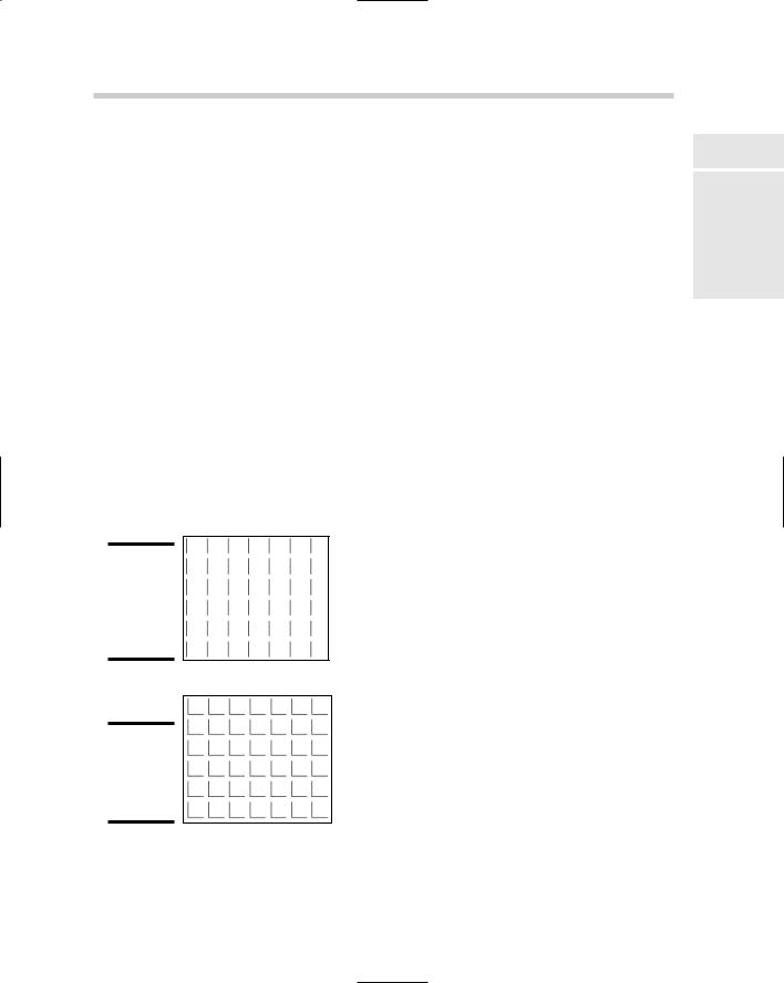
The second line draws all the horizontal dash segments of the hatch pattern. The dashes are drawn at a length of 0.2 and then followed by a space of 0.075 in length (see Figure 4-1). You can get an idea of how the hatch pattern looks if you draw a line that is 0.2 units going in the zero direction, and then copy that line over 0.275 in the zero direction. A descriptor line must not exceed 80 characters in length.
Figure 4-1:
The first part of the ANGLE hatch pattern.
Creating Custom Patterns 641
Line 3 of the ANGLE hatch pattern’s definition:
90,: The angle to be used for the hatch pattern data to follow on the same line
0,: The X-origin for the starting point of the hatch pattern
0,: The Y-origin for the starting point of the hatch pattern
0,: The X-offset used to determine the distance between line segments
.275,: The Y-offset used to determine the distance between line segments
.2,: The length of a dash
-.075: The length of a space
The third line draws all the vertical dash segments of the hatch pattern. The dashes are drawn at a length of 0.2 and then followed by a space of 0.075 in length (see Figure 4-2). You can get an idea of how the hatch pattern looks if you draw a line that is 0.2 units going in the zero direction and then copy that line over 0.275 in the zero direction. Do the same starting in the left corner of each of the new horizontal lines and draw the same size line at an angle of 90 degrees. Figure 4-3 shows what the completed ANGLE hatch pattern looks like when it is used to hatch a filled area.
Figure 4-2:
The second part of the ANGLE hatch pattern.
Figure 4-3:
Both lines of the ANGLE hatch pattern.
Book IX
Chapter 4
Deeper DelvingCustomization
into