Добавил:
Опубликованный материал нарушает ваши авторские права? Сообщите нам.
Вуз: Предмет: Файл:

AutoCAD & AutoCAD LT All-In-One Desk Reference For Dummies (2006)

.pdf
Скачиваний:
90
Добавлен:
17.08.2013
Размер:
17.7 Mб
Скачать

622 Creating a New Shortcut Key

Separator bars

Separator bars are used to organize and group commands together on a toolbar, pull-down menu, or shortcut menu. Separator bars can be inserted by right-clicking over a toolbar, pull-down menu, or shortcut menu and selecting Insert Separator. A separator bar is displayed as a horizontal or vertical line in the user interface, and as a short dash in the CUI editor.

Creating a New Shortcut Key

Shortcut keys allow you to access commands by using a keyboard combination that includes at least one modifier key and another key on the keyboard. Shortcut keys must use the Ctrl modifier key, but the Ctrl key can also be combined with the Shift or Alt key.

Follow these procedures to create a shortcut key:

1.From the menu bar, choose Tools Customize Interface.

The CUI editor is displayed.

2.In the Customizations In pane, click the plus sign next to the Keyboard Shortcuts node.

The Keyboard Shortcuts node is expanded and displays two additional categories: Shortcut Keys and Temporary Overrides.

3.In the Command List pane, select the command that you want to add to create a shortcut key for. Hold down the mouse button after selecting the command and drag it up to the Shortcut Keys node of the Customizations In pane. Release the mouse button when the cursor is over the node to add the command.

A new shortcut key is created based on the command dropped onto the node.

4.In the Properties pane, select the Key(s) field and click the button that appears on the right side of the field.

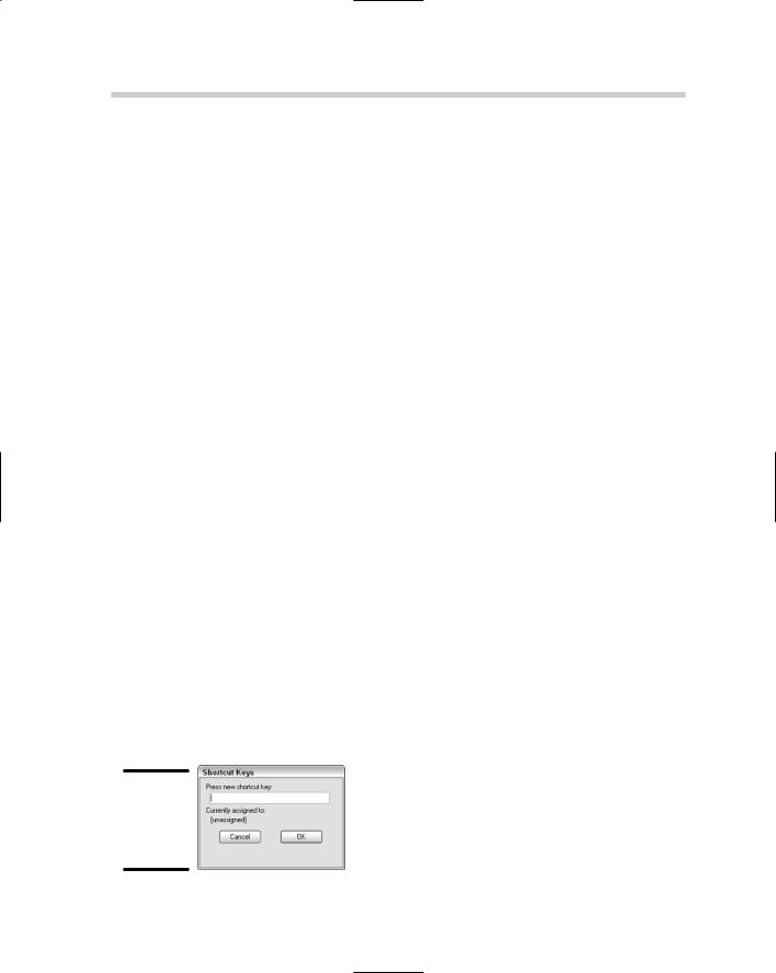
The Shortcut Keys dialog box is displayed (see Figure 3-10).

Figure 3-10:

The Shortcut Keys dialog box.

Customizing Double-Click Actions 623

5.In the Shortcut Keys dialog box, click in the Press New Shortcut Key text field.

The focus is set to the Press New Shortcut Key text field.

6.Press and hold down the CTRL key while pressing the other modifier key or the other key from the keyboard.

The key combination appears in the field. If the combination is already assigned to a different command, the other assignment is listed below the Press New Shortcut Key text field.

7.Click Assign to assign the key combination and click OK to exit the Shortcut Keys dialog box.

The Shortcut Keys dialog box is closed and the key combination is placed in the Key(s) property field.

8.Click Apply to stay in the CUI editor and save the changes, or click OK to exit the CUI editor and save the changes.

The changes are saved out to file.

Customizing Double-Click Actions

Double-click actions control what happens when you double-click an object in the drawing window. Double-clicking objects in the drawing allows you to quickly access a default edit command that is set up by object name like shortcut menus are. Double-click actions require the use of an object name to identify which command should be run when a user double-clicks an object in the drawing window.

The object name is the value listed by the LIST command or for special object names used for blocks and Xref objects. For information on the special object names used for blocks and Xrefs, see the section “Shortcut menus” and Table 3-3 earlier in this chapter.

AutoCAD has supported double-click editing since AutoCAD 2000i, but with the new release, you can customize which command is executed when an object is double-clicked in the drawing window.

Follow the procedures below to create a double-click action.

1.From the menu bar, choose Tools Customize Interface.

The CUI editor is displayed.

2.In the Customizations In pane, right-click the Double-Click Actions node and choose New Double-Click Action.

Book IX

Chapter 3

Customizingthe

Tools

624 Migrating and Transferring Customization

A new double-click action with the default name DoubleClick1 is created under the Double-Click Actions node.

3.In the Properties pane, change the double-click action’s Name.

The Name is used to locate the double-click action.

4.Enter the object name that the double-click action should be associated with in the Object Name property field.

The Object Name is used to identify which double-click action should be fired off when a user double-clicks an object in the drawing window.

5.In the Command List pane, select the command that you want to associate with the double-click action. Hold down the mouse button after selecting the command and drag it up to the new double-click action in the Customizations In pane. Release the mouse button when the cursor is over the node to add the command.

The command is now associated with the double-click action and the specified object name.

6.Click Apply to stay in the CUI editor and save the changes, or click OK to exit the CUI editor and save the changes.

The changes are saved out to file.

Migrating and Transferring Customization

Upgrading to a new version of AutoCAD has always been a somewhat timeconsuming problem with all of the customization and settings that need to be updated for a new release. Since AutoCAD 2005, AutoCAD has offered a utility called Migrate Custom Settings, which allows you to easily migrate a majority of your custom settings to a new release.

The utility migrates only settings, profiles, and customization located in specific support files but doesn’t do anything with menu customization.

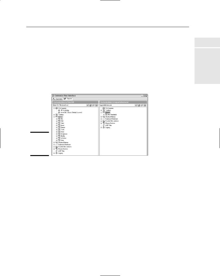
To resolve part of this problem, the CUI editor was designed with a Transfer tab. The Transfer tab allows you to migrate custom toolbars, pull-down menus, and other user interface elements to the new release.

Transferring customizations has always been a manual process: opening two customization files with a text editor, and then copying and pasting sections between the two files. The problem is that the approach of copying and pasting between two files can result in missing information or a file structure problem. The CUI editor resolves this problem by migrating your menu customization files forward to the .CUI file format and allowing you to move user elements by dragging and dropping right in the editor.

Migrating and Transferring Customization 625

Follow this procedure below to transfer customization from one customization file to another and to migrate customization from a legacy .MNU or .MNS file format:

1.From the menu bar, choose Tools Customize Interface.

The CUI editor is displayed.

2.Click the Transfer tab along the top of the CUI editor.

A second Customizations In pane is displayed on the right side of the CUI editor (see Figure 3-11).

Figure 3-11:

The Transfer tab of the CUI editor.

3.In the Customizations In pane on the right side, click the Open Customization File button.

The Open dialog box is displayed, allowing to you select a customization file (.CUI) or a menu file (.MNU/.MNS).

4.Select the type of file you want to open by choosing one of the options from the Files of Type drop-down list and browsing for the file you want to open.

The selected file’s name appears in the File Name text field.

5.Click Open.

The selected file is opened and displayed in the Customizations In pane. If a .MNU/.MNS file is selected, a .CUI file is automatically generated.

6.Expand the nodes of the two files and then drag and drop the user interface elements from the pane on the right to the one on the left.

The user interface elements are added in the file, along with any commands that are associated with the elements.

Book IX

Chapter 3

Customizingthe

Tools

626 Working with Partial and Enterprise Customization Files

The Legacy node contains tablets, image tile menus, and screen menu customization. If you have customized any of these sections in previous releases, don’t forget to transfer these elements too.

7.Switch back to the Customize tab and make any necessary changes to the transferred user interface elements.

You may need to add additional commands or even update workspaces to include or exclude toolbars and pull-down menus.

8.Click Apply to stay in the CUI editor and save the changes, or click OK to exit the CUI editor and save the changes.

The changes are saved out to file.

Working with Partial and Enterprise

Customization Files

Partial and enterprise customization files are ways of organizing and sharing customization between users. Whether you work in a large or small company, you can use an enterprise customization file to share standard company tools with all the members of your drafting teams. You might use tools in

an enterprise customization file to ensure layer and annotation standards, along with accessing company title blocks.

A partial customization file can contain a subset of customization when compared to the main customization file. The customization in the partial customization file is usually personal or task-based customization. You might use different partial customization files for different disciplines like Civil or Architectural.

Loading an enterprise customization file

Follow the procedures below to load an enterprise customization file.

1.From the menu bar, choose Tools Options.

The Options dialog box is displayed.

2.Click the Files tab, and click the plus sign next to the Customization Files node.

The Customization Files node expands and shows some additional nodes: Main Customization Files, Enterprise Customization File, and Custom Icon Location.

3.Click the plus sign next to the Enterprise Customization File node.

Working with Partial and Enterprise Customization Files 627

The Enterprise Customization File node expands and shows the current value; by default, the value is a period (.).

4.Select the current value and click Browse.

The Select a File dialog box is displayed.

5.Browse to the location of the customization (.CUI) file that you want to use for the enterprise customization file. Select the file and click Open.

The location of the selected file is added under the Enterprise Customization File node.

6.Click Apply to stay in the Options dialog box and save the change, or click OK to exit the Options dialog box and save the change.

The change is saved to the Windows Registry.

Loading a partial customization file

Follow the procedures below to load a partial customization file.

1.From the menu bar, choose Tools Customize Interface.

The CUI editor is displayed.

2.Click the Customize tab to make it current, and click Load Partial Customization File under the Customizations In pane.

The Open dialog box is displayed.

3.Browse to the location of the customization (CUI) file that you want to load as a partial customization file. Select the file and click Open.

The selected file is loaded as a partial customization file and is added to the Partial CUI Files node.

4.In the Warning box that appears, click OK.

The Warning box notifies you that any workspaces contained in the partial customization file won’t be available for use. The partial customization file is displayed in the Customizations In pane.

5.Select All Customization Files from the drop-down list at the top of the Customizations In pane to show all the loaded customization files.

The tree view in the Customizations In pane returns to its default display state.

6.Click Apply to stay in the CUI editor and save the changes, or click OK to exit the CUI editor and save the changes.

The changes are saved out to file.

Book IX

Chapter 3

Customizingthe

Tools

628 Book IX: Customizing AutoCAD

Chapter 4: Delving Deeper into Customization

In This Chapter

Working from a script

It’s all in the linetype

Getting familiar with shapes

Creating custom patterns

Getting to know the Express Tools

Many aspects of customizing AutoCAD are left untapped by most users. Much of this is due to the many ways AutoCAD can be customized

beyond just the user interface and appearance of the application window. Special file types and formats are used to automate tasks in AutoCAD and also to define custom linetypes and hatch patterns.

AutoCAD allows you to create script files that can be used to automate repetitive tasks through standard AutoCAD commands and options. Although AutoCAD comes with a variety of linetypes and hatch patterns, they don’t always cover everything that you might want to represent in your drawing. AutoCAD allows you to define your own custom linetypes and hatch patterns. All three of these customization options can be done with a text editor because they are plain text files. Unlike with customization files, you don’t need to use a special editor for these options.

Working from a Script

Have you ever received a set of drawings from a client that didn’t use the same drafting settings or conform to the CAD standards that you use? Or maybe you have had to manually update older drawings to match your company’s new CAD standards? Script files can be used for these tasks and much more.

630 Working from a Script

What is a script file?

A script file is used to automate functionality in AutoCAD using standard AutoCAD commands, options, and AutoLISP expressions. (AutoLISP expressions are not supported by AutoCAD LT, however.) A script file is a plain text file that contains commands and options in a specific format and has the file extension of .SCR. The structure of a script is very similar to the way AutoCAD commands and options are entered at the command line. Here is an example of a script file that does some basic drawing setup and demonstrates how to use comments in a script file:

; Created 11/13/05 by Lee Ambrosius LTSCALE 24

BLIPMODE 0 LIMITS 0,0 24,17 ZOOM EXTENTS

The opening line of the example is a comment that is ignored during the execution of the script. Comments don’t execute, but they can contain very important information that comes in handy when updates are made to the script file, for example. Comment lines begin with a semicolon, so AutoCAD ignores everything to the right of a semicolon.

The second line, LTSCALE 24, sets the linetype scale system variable to a value of 24. The space between LTSCALE and the value 24 is just like pressing the Enter key while entering values at the command line or dynamic input tooltip. AutoCAD automatically issues an Enter for each new line as the script is being evaluated.

The next line, BLIPMODE 0, turns blip markers off. The next line, LIMITS 0,0 24,17, is used to set the lower-left and upper-right drawing limits. The last line, ZOOM EXTENTS, is used to make sure the drawing is zoomed to its limits. At the end of the script file, make sure that there is a single blank line to let AutoCAD know when the script file ends.

Alternatively, commands and options can be on separate lines or on the same line; neither method is right nor wrong, but rather a preference. The following example shows the same script as previously shown with commands and options on separate lines.

;; Created 11/13/05 by Lee Ambrosius LTSCALE

24 BLIPMODE 0

LIMITS 0,0 24,17 ZOOM EXTENTS

Working from a Script 631

Using script files can offer both disadvantages and advantages. Here are some of the disadvantages:

There is no way to pause for user input during a command.

Dialog boxes can’t be called during the execution of the script.

Only a single script can be running in AutoCAD at a single time. You can’t call another script while a script is running.

AutoCAD does not ship with any sample scripts, which can make it difficult to get started creating your own scripts.

Here are some of the advantages:

The syntax is very basic and can be created by anyone who can use commands in AutoCAD.

Scripting is great for automating very basic and repetitive tasks.

Scripts require very minimal maintenance from release to release.

Scripts can be used transparently with AutoCAD commands.

Some commands bypass the use of dialog boxes. These commands are typically prefixed with a hyphen. For example, the –LAYER is the command line version of the LAYER.

AutoLISP expressions can be used in a script (if you’re not using AutoCAD LT and know how to use AutoLISP). Using AutoLISP with your scripts allows you to build much more complex and robust scripts.

Here are some commands specifically used for working with script files:

RSCRIPT: Repeats the last run script file.

RESUME: Continues a script that has been paused by the user pressing the Backspace key during the execution of the script.

DELAY: Pauses a script for the specified duration. The time duration is specified in milliseconds. One thousand milliseconds is equal to 1 second, and the maximum delay is a value of 32,767, which is equal to just a little longer than 32 seconds.

SCRIPT: Loads and runs a script file through a standard file select dialog box.

-SCRIPT: Loads and runs a script file from the command line.

Book IX

Chapter 4

Deeper DelvingCustomization

into