

AutoCAD & AutoCAD LT All-In-One Desk Reference For Dummies (2006)
.pdf612 Getting to Know the Customize User Interface Editor
Commands in the CUI editor
Commands in the CUI editor are not the same as an AutoCAD command like LINE. A command in the CUI editor can be made up of AutoCAD commands and options and AutoLISP expressions. After a command is created, it can be used in most of the user interface elements supported in the CUI editor.
Understanding a command macro
The core of a command in the CUI editor is its macro property. The macro is what is carried out when the command is selected from a toolbar button, pull-down menu item, or one of the other user interface elements that is referencing the command. Macros can contain special characters that are normally not allowed at the command line.
Table 3-1 lists the common special characters that can be part of a macro.
Table 3-1 |
Special Characters for a Macro |
Special Character |
Description |
|
|
; or [blank space] |
A semicolon or a space acts like the user pressed the Enter key. |
|
|
\ |
A backslash pauses for user input. |
|
|
_ |
An underscore translates the command or option so it can be |
|
used in an international version. |
* |
An asterisk repeats the command until Escape is pressed. |
|
|
^C |
Acts like the Escape key was pressed a single time. |
|
|
\\ |
Double backslashes allow for the use of the backslash in a |
|
macro. |
|
|
. |
A period forces AutoCAD to use the standard AutoCAD com- |
|
mand even if the command was undefined or redefined as |
|
something else. |
|
|
An example of a macro is
^C^C._line;\\\_c
The above macro starts the LINE command and allows the user to select a total of three points and then closes the object.
^C^C: Issues two different cancels to exit any running command.
._line: Starts the LINE command.
;: Issues an Enter to start the LINE command.

Getting to Know the Customize User Interface Editor 613
\\\: Requests the user for three different pieces of input. In this case, the input is in the form of points in the drawing.
_c: Uses the Close option for the LINE command to draw a line between the first and last points.
Creating a new command
Follow these steps to create a new command in the CUI editor:
1.From the menu bar, choose Tools Customize Interface.
The CUI editor is displayed.
2.Click the New button in the Command List pane.
A new command named Command1 is added to the list box by default, and the Button Image and Properties panes are displayed. If the name already exists, the next number in the sequence is used in the name.
3.In the Properties pane, change the command’s Name, Macro, and Element ID.
The Name is used to locate the command in the list under the Command List pane; the Macro defines what happens when the command is selected from the user interface; and the Element ID is used to uniquely identify the command through automation or when migrating the command between releases. For information on these and other properties, take a look at the description provided at the bottom of the Properties pane.
4.Click Apply to stay in the CUI editor and save the changes, or click OK to exit the CUI editor and save the changes.
The changes are saved to the file.
Assigning an image to a command
Assigning a small and large image to a command is optional. However, if you plan on using the command on a toolbar or pull-down menu, you might want to add images to it so that it matches many of the commands that come with AutoCAD. Follow these procedures to assign an image to a command:
1.From the menu bar, choose Tools Customize Interface.
The CUI editor is displayed.
2.Select a command from the list under the Command List pane.
The command is highlighted and its properties are displayed in the Properties pane.
3.In the Button Image pane, select either the Large, Small, or Both option. Then, click one of the images from the list.
Book IX
Chapter 3
Customizingthe
Tools
614 Getting to Know the Customize User Interface Editor
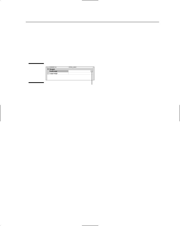
Based on the size option that you select, the value is populated in the Small and/or Large Image properties for the command. Optionally, you can also edit an existing image to create a new image for your command using the Edit button. If you have an image that you created in a separate program or one that already exists from a previous release, you can select the Small or Large Image fields under the Properties pane and then click the ellipsis button that is displayed (see Figure 3-6).
Figure 3-6:
Browsing for a custom image.
Ellipsis button
4.Click Apply to stay in the CUI editor and save the changes, or click OK to exit the CUI editor and save the changes.
The changes are saved to the file.
Assigning a help string to a command
Assigning a help string to a command is optional. However, a help string can give the users of the custom command a brief description of the command before they select it. Help strings appear in the status bar when the cursor is hovering over a command on a toolbar, pull-down menu, or shortcut menu.
Even though user interface elements like toolbars and pull-down menus have a description property that is never displayed to the user, so you can use it to track changes or revision information. Follow these procedures to assign a help string to a command:
1.From the menu bar, choose Tools Customize Interface.
The CUI editor is displayed.
2.Select a command from the list under the Command List pane.
The command should be highlighted and its properties are displayed in the Properties pane.
3.In the Properties pane, enter the help string value in the Description field.
4.Click Apply to stay in the CUI editor and save the changes, or click OK to exit the CUI editor and save the changes.
The changes are saved to the file.

Customizing Toolbars and Pull-Down and Shortcut Menus 615
Customizing Toolbars and Pull-Down
and Shortcut Menus
Because AutoCAD is a Windows-based application, it utilizes toolbars, pulldowns, and shortcut menus as part of its user interface. These are by far the most widely used UI elements in AutoCAD: They provide access to a majority of the drafting and editing commands.
Toolbars
Toolbars are small windows that can be docked along the edges of the application window or undocked (floating). They allow you to quickly access commands and options through buttons, drop-down lists, and flyouts. A flyout is a way to access the commands that are contained on another toolbar through a single button. They help keep the user interface looking cleaner than if the whole toolbar was visible.
Creating a new toolbar
Follow these steps to create a new toolbar:
1.From the menu bar, choose Tools Customize Interface.
The CUI editor is displayed.
2.In the Customizations In pane, right-click the Toolbars node and choose New Toolbar.
A new toolbar with the default name Toolbar1 is created under the Toolbars node.
3.In the Properties pane, change the toolbar’s Name and Alias.
The Name is used to locate the toolbar and is the value that is displayed in its caption toolbar; Alias is used to uniquely identify the toolbar through automation or when migrating the toolbar between releases. You can also change the properties under the Appearance section to control how the toolbar is initially displayed.
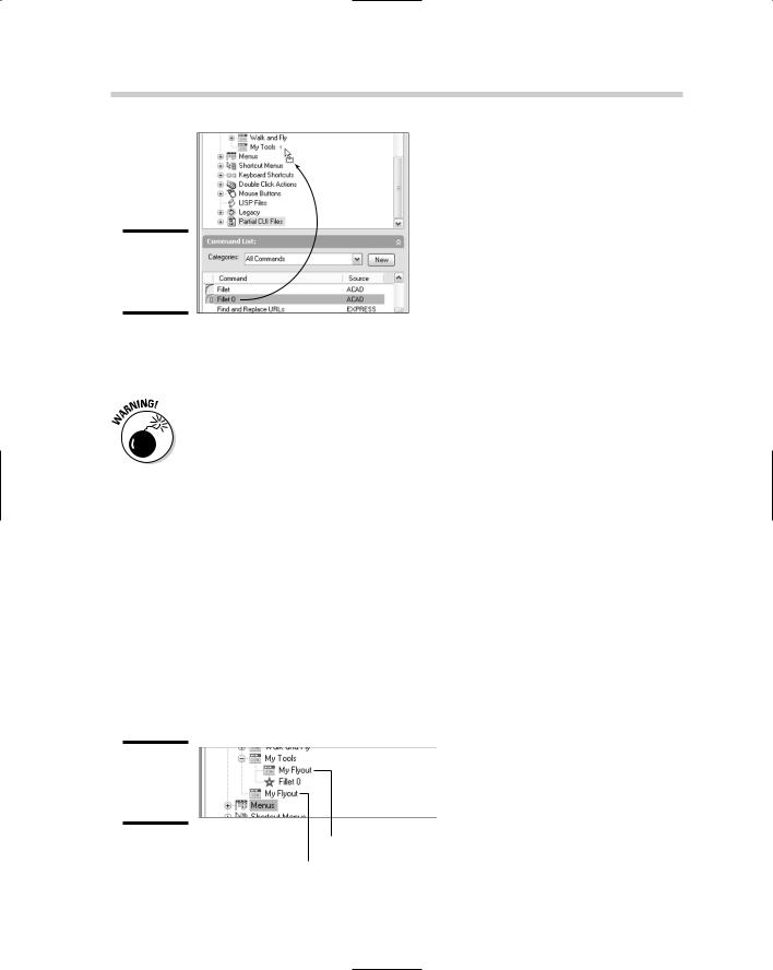
4.In the Command List pane, select the command that you want to add to the toolbar. Hold down the mouse button after selecting the command and drag it up to the new toolbar under the Toolbars node of the Customizations In pane. Release the mouse button when the cursor is over the toolbar to add the command (see Figure 3-7).
A reference to the command is added under the toolbar.
To select more than one command at a time to assign to a toolbar, hold down the Shift or Ctrl key while selecting commands.
Book IX
Chapter 3
Customizingthe
Tools
616 Customizing Toolbars and Pull-Down and Shortcut Menus
Figure 3-7:
Adding a command to a toolbar.
5.Click Apply to stay in the CUI editor and save the changes, or click OK to exit the CUI editor and save the changes.
The changes are saved to a file.
When adding a new user interface element such as a toolbar or pulldown menu, make sure to add a command to it before clicking Apply. Otherwise, the user interface element will not be saved to file.
Creating a new flyout
Follow these steps to create a flyout on a toolbar:
1. From the menu bar, choose Tools Customize Interface.
The CUI editor is displayed.
2.Create a new toolbar and change its Name and Alias in the Properties pane.
A new toolbar is created under the Toolbars node, and the Name and Alias properties are updated based on the provided values.
3.Click and drag the new toolbar above or below one of the commands on the toolbar that you want to create the flyout on.
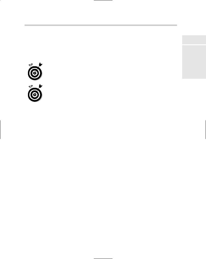
A new reference to the toolbar is created on the toolbar (see Figure 3-8).
Figure 3-8:
Adding a flyout to a toolbar.
Flyout (Toolbar Refere
Toolbar
Customizing Toolbars and Pull-Down and Shortcut Menus 617
4.Add commands to the new toolbar or flyout.
The new commands are displayed under the toolbar and flyout.
5.Click Apply to stay in the CUI editor and save the changes, or click OK to exit the CUI editor and save the changes.
The changes are saved out to file.
You can also right-click a toolbar and choose New Flyout to create a new toolbar and add the flyout reference to a toolbar. This method does introduce at least one additional step: When you rename the toolbar, the name of the flyout does not change automatically to match the toolbar name, so you will have to rename the flyout manually.
Commands and flyouts can be rearranged by dragging then up and down under their associated toolbar node.
Pull-down menus
Pull-down menus take up much less space than toolbars and contain a much wider selection of commands when compared to toolbars. Pull-down menus might not be as efficient as toolbars are, but they do offer a much greater set of organization. Similar to flyouts on a toolbar, pull-down menus support submenus. Submenus are different than flyouts because they are part of the pulldown menu and do not rely on another pull-down menu for their content.
Creating a new pull-down menu
Follow this procedure to create a new pull-down menu:
1.From the menu bar, choose Tools Customize Interface.
The CUI editor is displayed.
2.In the Customizations In pane, right-click the Menus node and choose New Menu.
A new pull-down menu with the default name Menu1 is created under the Menus node.
3.In the Properties pane, change the pull-down menu’s Name and Alias.
The Name is used to locate the pull-down menu and is the value that is displayed as the caption in the menu bar; and Alias is used to uniquely identify the pull-down menu through automation or when migrating the pull-down menu between releases.
4.Add any of the commands from the Command List pane that you want to be displayed under the pull-down menu.
Book IX
Chapter 3
Customizingthe
Tools

618 Customizing Toolbars and Pull-Down and Shortcut Menus
5.Click Apply to stay in the CUI editor and save the new command, or click OK to exit the CUI editor and save the new command.
The changes are saved to file.
Creating a new submenu
Follow these steps to create a submenu on a pull-down menu:
1.From the menu bar, choose Tools Customize Interface.
The CUI editor is displayed.
2.In the Customizations In pane, click the plus sign next to the Menus node.
The pull-down menus are displayed under the Menus node.
3.Right-click over the pull-down menu that you want to add a submenu to and choose New Sub-Menu.
A new submenu is added under the pull-down menu.
4.In the Properties pane, change the submenu’s Name.
The name of the submenu is displayed under the pull-down menu.
5.Add any of the commands from the Command List pane that you want to be displayed under the submenu.
6.Click Apply to stay in the CUI editor and save the changes, or click OK to exit the CUI editor and save the changes.
The changes are saved out to file.
Commands and submenus can be rearranged by dragging them up and down under their associated pull-down menu or submenu node.
Using special characters in a pull-down item name
Pull-down menu item names can contain special characters to control some of the behavior of the item. Table 3-2 lists some of the special characters that can be used in combination with a pull-down menu item name.
Table 3-2 |
Special Characters for a Pull-Down Item Name |
Special Character |
Description |
|
|
& |
An ampersand displays an underscore under the character that |
|
follows the ampersand. This allows users to access the pull- |
|
down menus by pressing the ALT modifier key plus the charac- |
|
ter that is underlined. |
|
|

Customizing Toolbars and Pull-Down and Shortcut Menus 619
Special Character |
Description |
&& |
Two ampersands together display an ampersand. |
|
|
~ |
A tilde disables the menu item, making it not selectable. |
|
|
!c or !. |
The character combination !c and !. puts a check mark in |
|
front of the pull-down menu item. |
|
|
\t (or tab character) |
Forces the text to the right side of the pull-down menu. This is |
|
often used to display the command alias for a command in the |
|
pull-down menu. |
Here’s an example of using a special character in the pull-down menu:
Save &As...
The A is the access key from the keyboard. To access the Save As command, press Alt+F to open the Files pull-down menu, and then press Alt+A.
Shortcut menus
Shortcut menus are used to display additional options specific to the selected object(s) or the active command or the current state of AutoCAD. Shortcut menus are displayed by pressing the right mouse button over the drawing window and based on the current value of the system variable SHORTCUTMENU. By default, the system variable SHORTCUTMENU is set to a value of 11, which indicates to AutoCAD that it should display shortcut menus when options are available for the active command, when no command is active and objects are selected, or when no command is active and no objects are selected.
Shortcut menus are created much like pull-down menus with one main exception: their aliases. Most shortcut menus are set up to work specifically with a specific command or object(s). To designate a shortcut menu to be used with a command, you use the alias syntax of COMMAND_commandname. An example of an Alias used to assign additional options to the LINE command’s rightclick menu is COMMAND_LINE. The alias is assigned to the Aliases property of the shortcut menu under the Properties pane of the Dynamic pane.
Shortcut menus can be associated to a specific object type, and when a single object of the designated object type is selected in the drawing window and the right mouse button is pressed, additional options are displayed on the right-click menu. To designate a shortcut menu to be used when an object of a certain type is selected, you use the alias syntax of OBJECT_ objectname. Just like the alias for a command based shortcut menu, the alias is assigned to the Aliases property of the shortcut menu. AutoCAD comes with many different shortcut menus. One example is the Hatch Object
Book IX
Chapter 3
Customizingthe
Tools

620 Customizing Toolbars and Pull-Down and Shortcut Menus
Menu, which uses the alias OBJECT_HATCH to display the Hatch Edit option on the right-click menu when a hatch object is selected in the drawing before you press the right mouse button.
To identify the object name for an object, you can use the LIST command on the object. The LIST command displays the object name in the AutoCAD Text Window. This sample shows the results of the LIST command in the AutoCAD Text Window after a line was selected:
|
LINE |
Layer: “0” |
|
|
|
|
|
|
Space: Model space |
|
|
||
|
Handle = 93 |
|
|
|
|
|
from |
point, X= |
14.5169 |
Y= |
7.9505 |
Z= |
0.0000 |
to |
point, X= |
27.3742 |
Y= |
15.9583 |
Z= |
0.0000 |
Length = |
15.1471, |
Angle in |
XY Plane = |
|
32 |
|
Delta X = 12.8573, Delta Y = |
8.0077, Delta Z = 0.0000 |
|||||
The object name is listed in the top-left of the returned values; in this case, LINE. An example of an Alias used to assign additional options to the Edit shortcut menu when a line object is selected is OBJECT_LINE. If you want to display a shortcut menu when more than one object of a specific object type is selected, you use the alias syntax of OBJECTS_objectname.
In some instances, the object name is not used, and that is because the LIST command returns the same object name for the different insert objects.
Table 3-3 lists the names to be used for blocks and external reference (Xref) objects.
Table 3-3 |
Special Object Names Used for Blocks and Xrefs |
Object Name |
Description |
|
|
BLOCKREF |
Block without attributes |
|
|
ATTBLOCKREF |
Block with attributes |
|
|
DYNBLOCKREF |
Dynamic block without attributes |
|
|
ATTDYNBLOCKREF |
Dynamic block with attributes |
|
|
XREF |
External reference |
|
|
Follow these procedures to create a shortcut menu.
1.From the menu bar, choose Tools Customize Interface.
The CUI editor is displayed.
2.In the Customizations In pane, right-click the Shortcut Menus node and choose New Shortcut Menu.
Customizing Toolbars and Pull-Down and Shortcut Menus 621
A new shortcut menu with the default name ShortcutMenu1 is created under the Shortcut Menus node.
3.In the Properties pane, change the shortcut menu’s Name.
The Name is used to locate the shortcut menu.
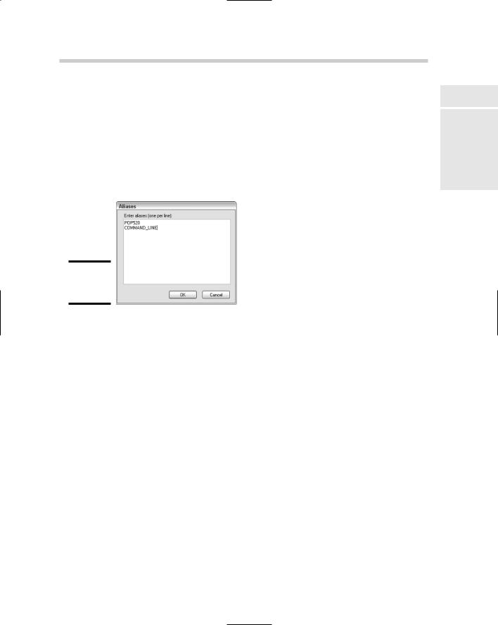
4.In the Properties pane, change the shortcut menu’s Aliases. To do this, click in the Aliases field and then click the button on the right side of the field.
The Aliases dialog box is displayed (see Figure 3-9).
Figure 3-9:
The Aliases dialog box.
5.In the Aliases dialog box, position the cursor behind the last alias in the list box and click. Press Enter to start a new line.
A new line is started for the new alias.
6.Enter the new alias to display additional options during an edit operation or a command.
Aliases are used to uniquely identify the shortcut menu through automation or when migrating the shortcut menu between releases. Aliases are used to determine the associated operation: edit or command.
7.Click OK to exit the Aliases dialog box.
The aliases that were in the Aliases dialog box are added to the Aliases property.
8.Add any of the commands from the Command List pane that you want to be displayed under the shortcut menu.
9.Click Apply to stay in the CUI editor and save the changes, or click OK to exit the CUI editor and save the changes.
The changes are saved out to file.
Book IX
Chapter 3
Customizingthe
Tools