AutoCAD & AutoCAD LT All-In-One Desk Reference For Dummies (2006)
.pdf


586 Book IX: Customizing AutoCAD

Chapter 2: Customizing
the Interface
In This Chapter
Getting to know the status bar
Training your toolbars and dockable windows to stay
Controlling the appearance and display of AutoCAD
Organizing your space
AutoCAD allows you to personalize the overall appearance of the application window and display settings that can affect performance. Many users personalize their AutoCAD session to reflect the way they like to work or the way they want things displayed on-screen. AutoCAD gives you a lot of control over the appearance of colors and font sizes throughout the applica-
tion window. The appearance settings include changing the background color of the drawing window and the crosshair color.
Not only does AutoCAD offer a variety of options to control colors of specific elements found in the application, but it also provides options to control whether certain user interface elements are displayed. Some of the features that you can control are the buttons located on the status bar and the icons that appear in the AutoCAD tray. This chapter explains how to control the appearance of AutoCAD and how to control user interface items such as toolbars and pull-down menus.
Getting Familiar with the Status Bar
AutoCAD takes full advantage of every space on its application window, and the status bar is no different. The status bar located at the bottom of the application window offers a variety of tools that allow for quick access to drafting settings and even notifications about changes that are taking place in the software and open drawings.
A number of different tools can be found on the status bar. These tools include the ability to toggle the dynamic input feature on and off and to change Object Snap settings to how lineweights are displayed in the drawing.
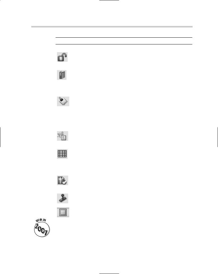
Table 2-1 lists the different buttons found on the status bar.
588 Getting Familiar with the Status Bar
|
Table 2-1 |
|
Status Bar Buttons |
|||||
|
Button |
Name |
Description |
|||||
|
|
|
|
|
|
|
|
|
|
|
|
|
|
|
|
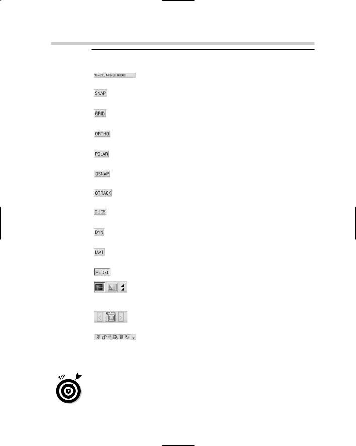
Coordinates |
Toggles between the different coordinate display |
|
|
|
|
|
|
|
||
|
|
|
|
|
|
|
|
settings. |
|
|
|
|
|
|
|
|
|
|
|
|
|
|
|
|
Snap Mode |
Toggles grid or polar snapping on and off. |
|
|
|
|
|
|
|
||
|
|
|
|
|
|
|
|
|
|
|
|
|
|
|
|
|
|
|
|
|
|
|
|
|
Grid Display |
Toggles the display of the grid on and off. |
|
|
|
|
|
|
|
||
|
|
|
|
|
|
|
|
|
|
|
|
|
|
|
|
|
|
|
|
|
|
|
|
|
Ortho Mode |
Toggles orthomode on and off. |
|
|
|
|
|
|
|
||
|
|
|
|
|
|
|
|
|
|
|
|
|
|
|
|
|
|
|
|
|
|
|
|
|
Polar Tracking |
Toggles polar tracking on and off. |
|
|
|
|
|
|
|
||
|
|
|
|
|
|
|
|
|
|
|
|
|
|
|
|
|
|
|
|
|
|
|
|
|
Object Snap |
Toggles running object snaps on and off. |
|
|
|
|
|
|
|
||
|
|
|
|
|
|
|
|
|
|
|
|
|
|
|
|
|
|
|
|
|
|
|
|
|
Object Snap |
Toggles object snap tracking on and off. |
|
|
|
|
|
|
|
||
|
|
|
|
|
|
|
Tracking |
|
|
|
|
|
|
|
|
|
|
|
|
|
|
|
|
|
|
|
|
|
|
|
|
|
|
Allow/Disallow |
Toggles dynamic UCS on and off. |
|
|
|
|
|
|
|
||
|
|
|
|
|
|
|
Dynamic UCS |
|
|
|
|
|
|
|
|
|
|
|
|
|
|
|
|
|
|
|
|
|
|
|
|
|
|
Dynamic Input |
Toggles dynamic input on and off. |
|
|
|
|
|
|
|
||
|
|
|
|
|
|
|
|
|
|
|
|
|
|
|
|
|
|
|
|
|
|
|
|
|
Show/Hide |
Toggles the display of lineweights on and off. |
|
|
|
|
|
|
|
||
|
|
|
|
|
|
|
Lineweight |
|
|
|
|
|
|
|
|
|
|
|
|
|
|
|
|
|
|
|
|
|
|
|
|
|
|
Model or Paper |
Toggles between model and paper space, and |
|
|
|
|
|
|
|
||
|
|
|
|
|
|
|
Space |
switches paper space layouts. If the layout tabs |
|
|
|
|
|
|
|
||
|
|
|
|
|
|
|
|
are not displayed three buttons are displayed and |
|
|
|
|
|
|
|
|
|
|
|
|
|
|
|
|
|
allow you to switch between model and paper |
|
|
|
|
|
|
|
|
space, along with switch between different paper |
|
|
|
|
|
|
|
|
space layout tabs. |
|
|
|
|
|
|
|
|
|
|
|
|
|
|
|
|
Minimize/Maximize |
Toggles between maximized and minimized view- |
|
|
|
|
|
|
|
||
|
|
|
|
|
|
|
and Viewport |
port states and allows you to switch between dif- |
|
|
|
|
|
|
|
Navigation |
ferent viewports. |
|
|
|
|
|
|
|
|
|
|
|
|
|
|
|
|
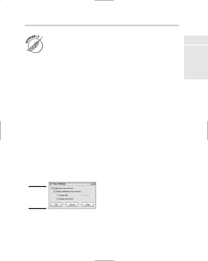
Icon Tray |
Displays the current notification icons for the fea- |
|
|
|
|
|
|
|
||
|
|
|
|
|
|
|
|
tures that are in use in the current session and |
|
|
|
|
|
|
|
|
drawing. It also allows you to access the Tray |
|
|
|
|
|
|
|
|
Settings. |
Many of the tools located on the status bar are not just toggles that turn a setting on or off, but they also allow for accessing the settings for the drafting tool. To change the settings of a drafting tool, right-click the status bar button and select Settings from the menu that appears. This displays a dialog box so you can change the behavior of the drafting tool.