

AutoCAD & AutoCAD LT All-In-One Desk Reference For Dummies (2006)
.pdf572 Customizing the AutoCAD Startup Process
options that AutoCAD does, so it is limited to startup options that don’t involve a programming language. Below is an overview of the different startup options available in AutoCAD:
Command line switches: Command line switches are parameters that can be defined with a shortcut file that is used to start AutoCAD. Command line switches can be used to perform a variety of tasks from starting with a specific drawing template to specifying the default Workspace to start with. For more information on command line switches, see “Using command line switches” later in this chapter.
Acad.LSP/Acaddoc.LSP/Acad2007.LSP/Acaddoc2007.LSP: These AutoLISP files are automatically loaded at the startup of AutoCAD. Neither Acad.LSP nor Acaddoc.LSP ships with the program but instead must be created by the user. For more information on the files Acad.LSP, Acaddoc.LSP, Acad2007.LSP, and Acaddoc2007.LSP, see Book X, Chapter 2.
Acad.MNL: Acad.MNL is an AutoLISP file that is associated with the customization file Acad.CUI and is loaded when the customization file is loaded. For more information on the Acad.MNL file, see Chapter 3 in this minibook.
Acad.RX: Acad.RX is a plain text file that defines which ObjectARX or ObjectDBX files should be loaded at startup. For more information on the Acad.RX file, see Book X, Chapter 2.
Acad.DVB: Acad.DVB is a VBA project that is automatically loaded at startup. For more information on the Acad.DVB file, see Book X, Chapter 2.
Appload – Startup Suite: The Startup Suite is a feature of the Application Load dialog box to load custom programs developed with AutoLISP, VBA, and ObjectARX. For more information on using the Startup Suite, see Book X, Chapter 2.
AutoCAD LT does not support AutoLISP, VBA, or ObjectARX programming; so the files Acad.LSP, Acaddoc.LSP, Acad2007.LSP, Acaddoc2007.LSP, Acad.MNL, Acad.RX, and Acad.DVB can’t be used to control its startup process. AutoCAD LT also doesn’t support the use of the APPLOAD command, which is used to load the different types of custom program files.
Using command line switches
Command line switches are used to control the behavior of AutoCAD when it is started from a desktop shortcut or the Start menu. You can customize the desktop shortcut so a specific drawing template is used to create the default drawing that is displayed when AutoCAD is started. You can also use command line switches to control which user profile is used when AutoCAD

Customizing the AutoCAD Startup Process 573
is started. This enables you to have multiple profiles for AutoCAD on the computer and use different desktop shortcuts to switch between them. When using command switches, make sure that you use “ “ (double quote marks) around the name of a drawing or drawing template file, workspace, or path that contains a space. If you don’t use “ “ for the name with a space, AutoCAD thinks it is another command line switch or argument.
Table 1-1 lists the different command line switches that are available for AutoCAD.
Table 1-1 |
Command Line Switches |
|
Switch and Syntax |
|
Description |
|
|
|
No switches |
|
If a list of drawings with spaces between each |
“...\acad.EXE” “drawing1” |
one is provided, AutoCAD opens each file in |
|
“drawingn” |
|
the list that it can find. |
|
|
|
/b |
|
The /b switch indicates to AutoCAD that it |
“...\acad.EXE” [“drawing”] |
should run the specified script file after it has |
|
/b “script” |
|
been started and the default or specified draw- |
|
|
ing has been opened. For more information on |
|
|
using script files, see Chapter 4 in this minibook. |
|
|
|
/c |
|
Allows you to specify the location of the |
“...\acad.EXE” /c “path” |
|
acad2007.CFG (acadlt2007.CFG) file. |
|
|
|
/ld |
|
Allows you to load an ObjectARX or ObjectDBX |
“...\acad.EXE” /ld “objectarx |
file at startup. Note: This command line switch |
|
or objectdbx file” |
|
is not available for AutoCAD LT. For more infor- |
|
|
mation on ObjectARX and ObjectDBX files, see |
|
|
Book X, Chapter 1. |
|
|
|
/nologo |
|
Suppresses the AutoCAD splash screen at |
“...\acad.EXE” /nologo |
|
startup. |
|
|
|
/nossm |
|
Suppresses the Sheet Set Manager when |
“...\acad.EXE” /nossm |
|
AutoCAD starts up, if it was open when |
|
|
AutoCAD was closed. Note: This command line |
|
|
switch is not available for AutoCAD LT. For |
|
|
more information on the Sheet Set Manager, |
|
|
see Book VII, Chapter 2. |
/p |
|
Controls which AutoCAD user profile is used at |
“...\acad.EXE” /p |
|
startup. You can also specify an exported pro- |
“profile_name” |
|
file file with the .ARG extension in place of the |
|
|
profile name. This loads the profile from the |
ARG file and makes it current. Note: This command line switch is not available for AutoCAD LT. For more information on user profiles, see “Changing Options and Working with User Profiles” later in this chapter.
Book IX
Chapter 1
Basics TheCustomizingAutoCAD
of
(continued)

574 Customizing the AutoCAD Startup Process
Table 1-1 (continued)
Switch and Syntax |
Description |
/r |
Restores the system-pointer device settings |
“...\acad.EXE” /r |
and creates a backup of the current configura- |
|
tion file. Note: This command line switch is not |
|
available for AutoCAD LT. |
/s |
Allows you to specify additional support paths |
“...\acad.EXE” /s “path” |
that might not be defined under the Files tab of |
|
the Options dialog box. Note: This command |
|
line switch is not available for AutoCAD LT. |
|
For more information on support paths and |
|
options, see “Changing Options and Working |
|
with User Profiles” later in this chapter. |
|
|
/set |
Allows you to specify a Sheet Set file that |
“...\acad.EXE” /set |
should be loaded at startup. Note: This com- |
“sheet_set” |
mand line switch is not available for AutoCAD |
|
LT. For more information on the Sheet Set |
|
Manager, see Book VII, Chapter 2. |
|
|
/t |
Allows you to specify a drawing template that |
“...\acad.EXE” /t |
should be used to create the default drawing |
“drawing_template.DWT” |
that is created when AutoCAD is started. For |
|
more information on drawing templates, see |
|
Book I, Chapter 3. |
|
|
/v |
Allows you to specify a specific view in the |
“...\acad.EXE” “drawing.DWG” |
drawing that is being opened. For more infor- |
/v “kitchen” |
mation on views, see Book II, Chapter 3. |
/w |
Allows you to specify a Workspace that should |
“...\acad.EXE” |
be loaded upon startup. The Workspace must |
“workspace” |
exist in one of the loaded customization (.CUI) |
|
files. For more information on Workspaces, see |
|
Chapter 3 in this minibook. |
The /w command line switch is new in AutoCAD 2007 and AutoCAD LT 2007.
Creating a new desktop shortcut
Follow these steps to create a new desktop shortcut:
1.Right-click over the Windows Start button and click Explore.
Windows Explorer is launched.
2.Navigate to the AutoCAD install folder. By default, AutoCAD is installed in the folder C:\Program Files\AutoCAD 2007 (AutoCAD LT 2007).
The contents of the AutoCAD 2007 (AutoCAD LT 2007) folder should be displayed in the pane on the right side of Windows Explorer.
Customizing the AutoCAD Startup Process 575
3.Locate the file Acad.EXE (or Acadlt.EXE) and right-click the filename.
The file should highlight and a shortcut menu should appear.
4.From the shortcut menu, click Copy.
The information about the executable file is copied to the Windows Clipboard.
5.Minimize all open applications until you see the Windows desktop.
6.Right-click over an empty area of the desktop and click Paste Shortcut from the shortcut menu.
A new desktop shortcut should be created titled Shortcut to acad.EXE (or Shortcut to acadlt.EXE).
You can right-click an empty area of the Windows taskbar and click Show the Desktop instead of minimizing all application windows one at a time. If you have a keyboard with a flying Windows key on it, you can also press and hold down the key while pressing the M key on the keyboard to minimize all application windows.
Modifying a desktop shortcut
Follow this procedure below to modify the AutoCAD desktop shortcut and add a command line switch:
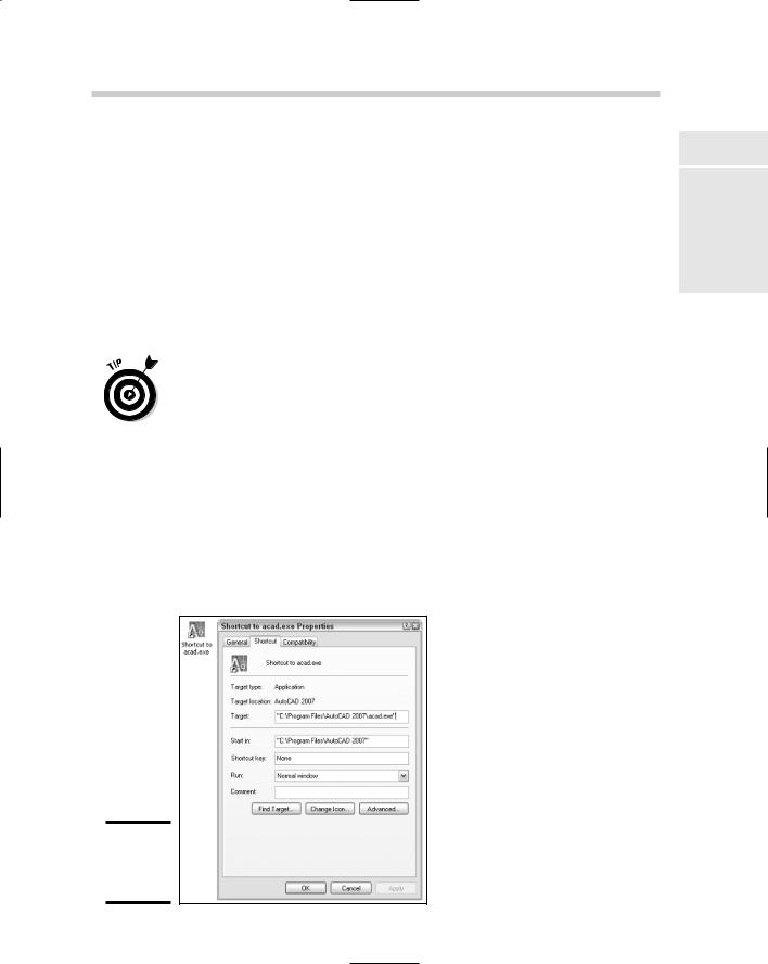
1.Right-click the AutoCAD desktop shortcut and click Properties.
The Properties dialog box (see Figure 1-1) for the desktop shortcut is displayed.
Figure 1-1:
The shortcut Properties dialog box.
Book IX
Chapter 1
Basics TheCustomizingAutoCAD
of
576 Customizing the AutoCAD Startup Process
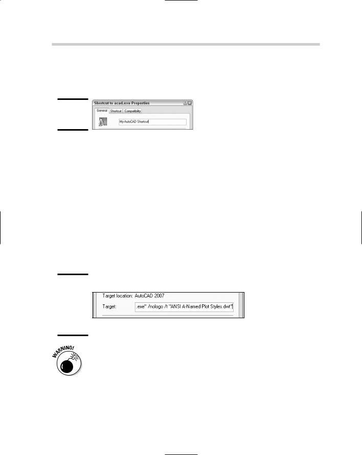
2.Click the General tab and enter a new name for the desktop shortcut in the text field next to the icon (see Figure 1-2).
The name is displayed on the desktop below the shortcut.
Figure 1-2:
The shortcut name field.
3.Click the Shortcut tab and locate the Target text field just above the middle of the Shortcut Properties dialog box.
The Target text field controls the string that is executed when the shortcut is double-clicked with the pointing device.
4.Position the cursor to the right of the text in the Target text field and click.
The cursor should be located to the right of the text C:\Program Files\ AutoCAD 2007\acad.EXE (or AutoCAD LT 2007\acadlt.EXE).
5.Enter a space and then the text /nologo /t “ANSI A -Named Plot Styles.DWT” (see Figure 1-3).
The /nologo switch suppresses the splash screen and the /t switch with the specified drawing template is used to create the default Drawing1.DWG file.
Figure 1-3:
The shortcut target field with command line switches.
If a value that is used with a command line switch has a space, you must surround the value with double quote marks like in Step 5. This applies to values such as file paths or a profile name.
Changing Options and Working with User Profiles 577
6.Click OK to save the changes and exit the shortcut Properties dialog box.
7.Double-click the desktop shortcut to start AutoCAD.
You should notice that no splash screen is displayed and Drawing1.DWG now has a title block based on the one that is defined in the ANSI A - Named Plot Styles drawing template.
Changing Options and Working with User Profiles
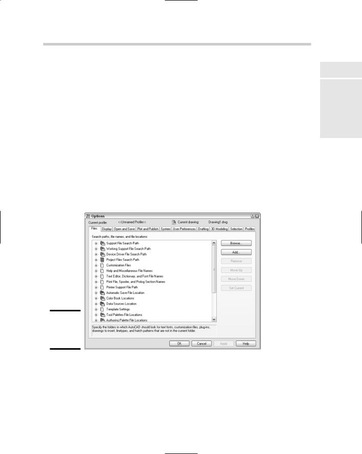
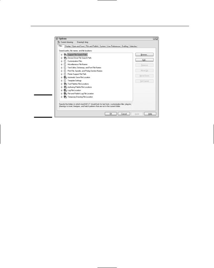
The Options dialog box (Figure 1-4) is used as the central hub to control many of the behavioral attributes of AutoCAD. From the Options dialog box, you can control drafting settings for grips, selection methods, and the appearance of AutoSnap markers that are displayed when using running object snaps. The Options dialog box also contains settings that control the appearance of AutoCAD and where it looks to find its support files. Figure 1-5 shows the Options dialog box in AutoCAD LT.
Figure 1-4:
The Options dialog box – AutoCAD.
Book IX
Chapter 1
Basics TheCustomizingAutoCAD
of
578 Changing Options and Working with User Profiles
Figure 1-5:
The Options dialog box – AutoCAD LT.
Launching the Options dialog box
To launch the Options dialog box, use one of these methods listed:
Tools menu: Choose Tools Options.
Keyboard input: Type OPTIONS at the command line and press Enter.
Command alias: Type OP and press Enter.
Right-click shortcut menu: Right-click over the command line, and then select Options from the shortcut menu that appears. You can also rightclick an empty area of the drawing window and choose Options from the shortcut menu that appears.
Overview of AutoCAD options
The Options dialog box has way too many options for us to list each one individually. Instead, here is an overview of the types of options found under each one of the tabs found in the dialog box:
Files: Contains the folders that the program uses to search for support, menu, user-defined, and other files.
Display: Contains options that control how a drawing is viewed, along with settings that control the appearance of the program’s application window.

Changing Options and Working with User Profiles 579
Open and Save: Contains options that control the processes of opening and saving files.
Plot and Publish: Contains options that are used for outputting a drawing or a set of drawings to hard copy or electronic formats.
System: Contains options that control the pointing device and some other general options that control the behavior of the program.
User Preferences: Contains options that are unique to users and the way they work with certain features found in the program.
Drafting: Contains options that affect how things like points are selected in a drawing or how you are prompted for input.
Selection: Contains options that affect how objects are selected and the behavior of grip editing.
Profiles: Contains options to create and manage user profiles.
The Options dialog boxes for AutoCAD and AutoCAD LT have numerous differences; one of the biggest is that AutoCAD LT does not support user profiles.
Some options are stored in the drawing, whereas others are not saved at all or are stored in the Windows Registry. The options that can be set through the Options dialog box and are stored in the drawing are denoted with the small drawing file icon to the left of the option.
Working with user profiles
A user profile is used to store options that are defined in the Options dialog box by a given name. This allows you to access a specific configuration of options for task-based procedures or to share them with others in your company. User profiles are stored with the Windows profile in the Registry.
Creating a user profile
Follow this procedure to create a new user profile in AutoCAD.
1.Launch the Options dialog box using one of the previously described methods.
The Options dialog box is displayed.
2.In the Options dialog box, click the Profiles tab along the top.
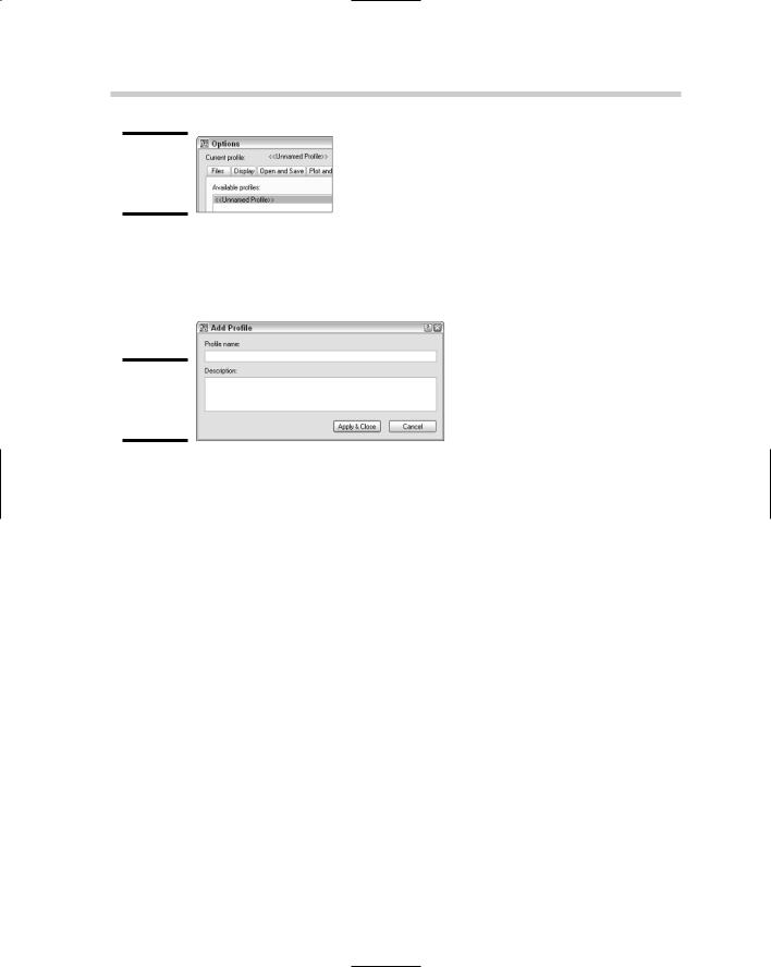
The options for working with profiles should be displayed. In the upperleft corner of the Options dialog box, you can find out which of the profiles is current (see Figure 1-6).
Book IX
Chapter 1
Basics TheCustomizingAutoCAD
of
580 Changing Options and Working with User Profiles
Figure 1-6:
Identify the current profile.
3.Click the Add to List button.
The Add Profile dialog box (see Figure 1-7) is displayed.
Figure 1-7:
The Add
Profile dialog box.
4.Enter a name in the Profile Name text field and a description in the Description text field.
The name is what appears in the Available Profiles list and what can be used with the /p command line switch to load a profile at startup.
5.Click Apply & Close to add the profile to the list.
The Add Profile dialog box closes, the new user profile is added to the Available Profiles list, and you are returned to the Options dialog box.
6.Click OK to exit the Options dialog box.
Setting a user profile current
Follow this procedure to set a user profile current:
1.Launch the Options dialog box using one of the previously described methods.
2.In the Options dialog box, click the Profiles tab along the top.
3.Select the user profile from the Available Profiles list that you want to set current and click Set Current.
The user profile is set current and the options are applied to AutoCAD.
4.Click OK to exit the Options dialog box.
Changing Options and Working with User Profiles 581
Exporting and importing a user profile
Profiles can be exported out of AutoCAD, which enables you to back them up in case you need to reinstall AutoCAD, or to share them with others in your company. Follow this procedure to export a user profile and then import it back into AutoCAD:
1.Launch the Options dialog box using one of the previously described methods.
2.In the Options dialog box, click the Profiles tab along the top.
3.Select the user profile from the Available Profiles list and click Export.
The Export Profile dialog box is displayed. This dialog box is a standard Windows file navigation dialog box.
4.In the Export Profile dialog box, specify a location to export the profile to and enter a name for the file in the File Name text field.
By default, AutoCAD uses the name of the drawing file for the name of the file that the user profile is being exported to.
5.Click Save.
The user profile is exported out using the specified filename and location, and you are returned to the Options dialog box. The user profile file has the file extension of .ARG.
6.In the Options dialog box, click Import.
The Import Profile dialog box is displayed. This dialog box is a Windows standard file navigation dialog box.
7.In the Import Profile dialog box, browse to the location that you have saved the exported file to and select the user profile file that you want to import.
8.Click Open.
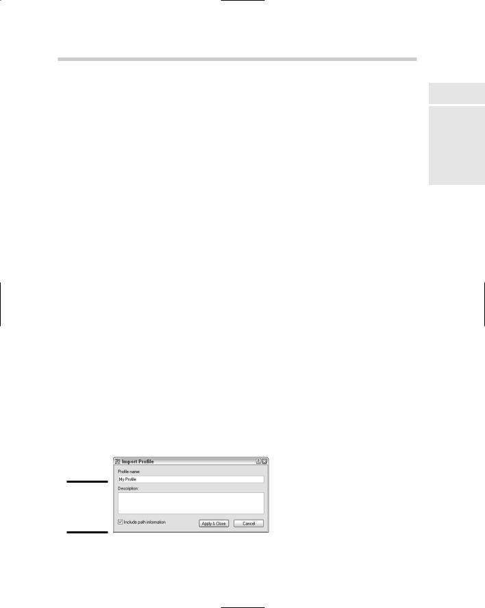
The Import Profile dialog box (see Figure 1-8) is displayed; this box is different from the previous Import Profile dialog box.
Figure 1-8:
The Import Profile dialog box.
Book IX
Chapter 1
Basics TheCustomizingAutoCAD
of