Creating a DWF file
Autodesk provides a number of ways for you to create a DWF file, whether you are using AutoCAD or one of the many different Autodesk products. From inside AutoCAD, you use the PLOT and PUBLISH commands to create a DWF file. The following procedure uses the File menu to start the PLOT command and create a DWF file.
1.Choose File Plot.
The Plot dialog box is displayed.
2.In the Plot dialog box, choose DWF6 ePlot.pc3 from the Printer/Plotter drop-down list.
The DWF6 ePlot.pc3 plot device becomes active.
3.Click the Properties button just to the right of the Printer/Plotter drop-down list.
The Plotter Configuration Editor – DWF6 ePlot.pc3 dialog box appears. From here, you can access various properties for the device.
4.In the Plotter Configuration Editor – DWF6 ePlot.pc3 dialog box, select Custom Properties from the tree view and then click the Custom Properties button under the Access Custom Dialog area.
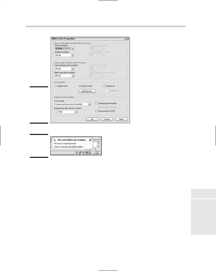
The DWF ePlot Properties dialog box appears (see Figure 4-11). From this dialog box, you can specify various options related to creating a DWF file. Properties range from embedding fonts to whether layer names and on/off states are maintained to the files resolution settings.
5.In the DWF ePlot Properties dialog box, specify the options as necessary and then click OK twice to return to the Plot dialog box.
The changes are saved, and the DWF ePlot Properties and Plotter Configuration Editor – DWF6 ePlot.pc3 dialog boxes are closed.
6.In the Plot dialog box, specify the necessary options for your plot and then click OK.
The Browse for Plot File dialog box appears, allowing you to specify the name of the DWF file that will be created and the location where you want to create it.
7.In the Browse for Plot File dialog box, enter the name for the file and the location where you want to save it, and then click Save.
The DWF file is created in the specified location with the name that you entered. After the plot is created, a notification balloon appears to inform you that the Plot and Publish job has completed (see Figure 4-12). You can right-click over the Plot/Publish icon and select View DWF File to view the DWF file.

These files are not embedded in a document or part of a Web page. You can launch the viewer to view a DWF file by double-clicking the file in Windows Explorer.
The following procedure uses the free Autodesk DWF Viewer to open a DWF file.
1.Choose Start (Windows button) [All] Programs Autodesk and
Autodesk DWF Viewer.
The Autodesk DWF Viewer application is launched and by default displays the Getting Started page.
2.From the Getting Started page of the Autodesk DWF Viewer, choose File Open.
The Open File dialog box appears.
3.Browse to and select the DWF file you want to open. Click Open.
The selected file opens in the Autodesk DWF Viewer. After the file opens, you can pan and zoom around in the file and view the drawing properties published with the file.
Electronically marking up a DWF file
You can use DWF files with Autodesk DWF Composer to communicate changes (or revisions as they are often called) to a drafter. Autodesk DWF Composer contains a number of mark-up and commenting tools that range from creating a simple line to much more complex tools that allow for the creation of revision clouds around areas in the file. As mark-up and commenting objects are added, Autodesk DWF Composer records by whom and when they were added to the DWF file.
Once the markups and comments have been added to the DWF file by using Autodesk DWF Composer, you can send them back to a drafter to make the necessary changes or plot them off with the viewer. If the DWF file with the markups is sent back to a drafter who has access to the original drawing files, the markups can be imported into AutoCAD by using the Markup Set Manager palette.
Even though you can attach DWF files in AutoCAD, the markups are not imported and managed this way. AutoCAD provides a feature that is specifically designed to work with markups that were created with Autodesk DWF Composer, called Markup Set Manager. You launch the Markup Set Manager palette by using the MARKUP command. You can start this command in a number of ways:
Working with DWFs 565
Tools menu. Choose Tools Palettes Markup Set Manager.
Standard toolbar. Click the Markup Set Manager button on the CAD Standards toolbar.
Keyboard input. Type MARKUP and press Enter.
Shortcut Key. Press the key combination CTRL+7.
Command alias. Type MSM and press Enter.
Because Autodesk DWF Composer must be purchased separately, explaining how to create markup files and exchange them between Autodesk DWF Composer and AutoCAD is beyond the scope of this book. To find out more about using Autodesk DWF Composer to exchange DWF files and create markups, visit Autodesk’s Web site at www.autodesk.com/dwfcomposer.
Book VIII
Chapter 4
566 Book VIII: Collaboration
Chapter 1: The Basics of
Customizing AutoCAD
In This Chapter
Understanding the benefits of customizing AutoCAD
Customizing the AutoCAD startup process
Changing options and using user profiles
Creating and managing command aliases
Book IX is designed to help both AutoCAD and AutoCAD LT users improve their workflow through customization. The majority of the cus-
tomization options in Book IX are available in both AutoCAD and AutoCAD LT. Although AutoCAD LT supports a majority of the same customization options that AutoCAD does, there are exceptions. In this chapter, we mention these exceptions as they arise.
Have you ever wanted to learn how to start AutoCAD with a specific user profile already set current, or wanted to add your own custom command aliases? Maybe you already understand some of the available customization options but want to find out more about some you don’t use. Whatever the reason, customization can help you to improve accuracy and efficiency during the design process. Customization isn’t necessarily easy, but you don’t have to be a programmer to take advantage of these features either.
Why Customize AutoCAD?
AutoCAD is one of the most popular design and drafting programs out on the market today, but if you take a good look at the program, you’ll probably find that you’ve barely scratched the surface of what it can do. AutoCAD is designed to be very flexible and to adapt to the way you work. And if you don’t like the layout of the program, you can always change the way it looks.
Not only can you customize the user interface — often referred to as the UI — but you can also make changes to help reduce repetitive tasks and ensure that CAD standards are followed. The level of customization that AutoCAD
570 Why Customize AutoCAD?
offers is much more dynamic than many of the other programs out on the market. Customizing AutoCAD is often confused with topics like AutoLISP and VBA. These languages can be used to customize AutoCAD, but they fall into the category of programming and are covered later in Book X. You can customize AutoCAD without resorting to any programming.
AutoCAD offers a large variety of customization options; so many, in fact, that you will probably not use all of them. The options range from creating new ways to start commands to defining how AutoCAD starts up. Customization can also be used to define the appearance of line work in a drawing with custom linetypes or custom patterns for hatched areas. Below is an overview of the different customization options available in AutoCAD:
Blocks: Blocks are a form of customization because you are creating reusable content. This is one of the most natural forms of customization because you are extending the capabilities of AutoCAD without really knowing that you are customizing it. For more information on blocks, see Book VI, Chapters 2 and 3.
Drawing templates: You might not have thought of drawing templates as a customization, but they are used to preset drafting options and the appearance of a base drawing, so they are a type of customization. For more information on drawing templates, see Book I, Chapter 3.
Command aliases: Command aliases are used to allow faster access to commands from the command line. Many of the commonly used commands in AutoCAD have a command alias associated to them. An example of a command alias is L for the command LINE. For more information on command aliases, see “Creating and Managing Command Aliases” later in this chapter.
User profiles: User profiles are used to control the appearance of AutoCAD, drafting settings, and where AutoCAD should look to find core and user-customized files. For more information on user profiles, see “Changing Options and Working with User Profiles” later in this chapter.
Diesel: Diesel is a macro language that can be used to customize the status bar area of AutoCAD and to control parts of the user interface, like pull-down items. For more information on using Diesel, see Chapter 2 of this minibook.
User interface: The user interface refers to the visual aspect of AutoCAD’s controls, such as toolbars and pull-down menus, among other features. Many components of the user interface are controlled by an external file that is customized using the Customize User Interface
(CUI) editor. For more information on customizing the user interface, see Chapter 3 of this minibook.

Customizing the AutoCAD Startup Process 571
Tool Palettes: Tool Palettes are one of the newest methods of customizing AutoCAD, and they provide ways to organize and access reusable content like blocks, hatches, and command tools. Tool Palettes allow for multiple levels of organization, so you can access the right tool or content quickly based on the task that you are trying to perform. For more information on customizing Tool Palettes, see Book VI, Chapter 4.
Scripts: Script files are structured files that allow you to automate standard commands and options. Because these files are based on commands and options that you already use, they are fairly easy to create to reduce repetitive tasks. For more information on script files, see Chapter 4 of this minibook.
Linetypes: Linetypes are used to control the appearance of line work in a drawing file when it is viewed and plotted. AutoCAD comes with a variety of default linetypes, but you might need to create your own for a project to represent something like a cable line or a flow direction. For more information on linetypes, see Chapter 4 of this minibook.
Shapes: Shapes are one of the earliest forms of blocks that AutoCAD offered, but they still serve a purpose in AutoCAD even today. Shapes can be found in complex linetypes. For more information on shapes, see Chapter 4 of this minibook.
AutoCAD LT does not support the creation of custom Shape files because it does not support the COMPILE command.
Hatch patterns: Hatch patterns are used to control the appearance of filled or hatched areas. AutoCAD ships with a number of default patterns, but you might want additional hatch patterns to represent things like wood or other patterns not available by default. For more information on hatch patterns, see Chapter 4 of this minibook.
Command line switches: Command line switches are used to control some of the AutoCAD startup behavior. For more information on command line switches, see “Using command line switches” later in this chapter.
Customizing the AutoCAD Startup Process
AutoCAD offers a number of options to control how it starts up. Some of these options can be controlled through the desktop shortcut (or icon), whereas others are controlled through specially named files.
Startup options
Book IX
Chapter 1
Basics TheCustomizingAutoCAD
of
Several different startup options are available to you. Some, but not all, of these use a programming language. AutoCAD LT doesn’t support the programming