

AutoCAD & AutoCAD LT All-In-One Desk Reference For Dummies (2006)
.pdf22 Touring the AutoCAD Interface
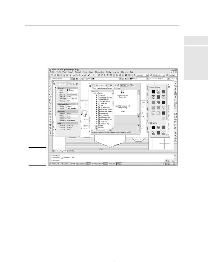
toolbar, and at the right, the Modify and Draw Order toolbars. Finally, the Workspaces toolbar is floating somewhere near the top of the drawing area. Assuming you installed the Express Tools, you also see the three Express Tools toolbars floating near the top of the drawing area (see Figure 2-5).
Docked toolbars |
Floating toolbars |
Figure 2-5:
The default toolbar arrangement.
Unlike the menu system, the toolbars contain virtually all of AutoCAD’s commands. Toolbars can easily be customized — we show you how in Book IX — and are a highly efficient way of working with the program.
You already know how to close toolbars. (Hint: It starts with an X.) The easiest way to open toolbars is to put your mouse pointer over any tool button and right-click. (Don’t left-click or you’ll run the command.) AutoCAD displays a menued list of all toolbars; just click the one you want to open.
To save constantly opening and closing toolbars, or having so many toolbars open that you can’t see your drawing, you can open a bunch and then save them as a workspace. We tell you how in Book IX.
Touring the AutoCAD Interface |
23 |
Palettes
AutoCAD 2004 introduced palettes, and they’ve become increasingly sophisticated with each release. Some dialog boxes from earlier releases, such as Object Properties, have been converted to palettes. Palettes have the advantage of staying open on-screen while you do other things (see Figure 2-6).
Figure 2-6:
A pile of palettes.
You open and close palettes by clicking their tool buttons on the Standard toolbar, or use the Ctrl+key combination indicated in the following list. AutoCAD’s tool palettes consist of the following:
Properties. List all properties of selected objects, including layer, color, coordinates, style, and so on. (Ctrl+1). We fill you in on object properties in Chapter 5 of this minibook.
AutoCAD DesignCenter. Use to copy objects from one drawing to another (Ctrl+2). We tell you more about DesignCenter in Book VI.
Tool palettes. Use to access frequently used blocks, hatch patterns, and commands (Ctrl+3). For more on tool palettes, see Book VI.
Book I
Chapter 2
the NavigatingInterface AutoCAD
24 Touring the AutoCAD Interface
External References. The old Xref Manager and Image Manager dialog boxes have been combined into a new palette called, simply, External References. The new DWF Underlay feature is also managed from this palette. We give you the scoop on working with external reference drawings, raster images, and DWF underlays in Book VI.
Sheet Set Manager. Set up drawing sets by project for printing and electronic distribution (Ctrl+4). We tell you all about sheet sets and the Sheet Set Manager in Book VII.
Info Palette. Get Quick Help in the middle of commands; lock topics so they stay open as you follow the steps (Ctrl+5). For more info on the Info Palette, see “Using the Info Palette” later in this chapter.
DBConnect Manager. Connect AutoCAD drawings with external database files (Ctrl+6). This is a pretty esoteric area of AutoCAD, and we don’t cover it in this book.
Markup Set Manager. Review electronic markups of DWF files and incorporate necessary changes (Ctrl+7). Check out Book VIII for more on this feature.
Calculator. Just like the one in your desk drawer, only it works with stuff you’ve drawn as well as numbers (Ctrl+8). We cover AutoCAD’s nifty built-in calculator in Book VI.
A great new feature in AutoCAD 2007 is anchorable palettes. (Docked palettes? Anchored palettes? Could there be some sailors at Autodesk?) An anchored palette is a combination of a docked palette that doesn’t keep moving around on you, and an auto-hide palette that rolls out of the way when you’re not using it. To anchor any palette, right-click its title bar and choose Allow Docking. Then right-click the title bar again and choose Anchor Left < or Anchor Right >. The palette scrolls shut and anchors its title bar at the left or right edge of the display.
Okay, at this point you’re probably dying to know what Ctrl+9 and Ctrl+0 do, so go ahead and try them. And don’t panic when parts of your screen disappear — remember, these are toggles, so just press Ctrl+9 again to bring
back the command window, and Ctrl+0 to restore all your toolbars, title bars, and other screen components. We tell you about the command window a couple of paragraphs ahead.
Pressing Ctrl+0 issues a command called CLEANSCREENON, which maximizes the program window, and turns off the program title bar and all toolbars, and hides the Windows taskbar. This gives you the largest possible drawing area on-screen, but leaves you with only the menu system and the keyboard to work with. Press Ctrl+0 again to run the CLEANSCREENOFF command (aren’t you glad you don’t have to type command names?) to bring all those things back again.
Touring the AutoCAD Interface |
25 |
If you’ve tried out AutoCAD 2007’s 3D Modeling workspace, you’ll have encountered a brand-new interface item called the Dashboard. The Dashboard is a combination tool palette and super-toolbar that’s configured for working in 3D. We cover the Dashboard (and 3D in general) in Book V. There are several new palettes — Lights, Materials, Visual Styles, and Rendering — that we also cover in Book V rather than in this introductory section, which deals with 2D drafting.
Drawing area
That big black (or maybe white) area that occupies almost 90% of your AutoCAD window is the drawing area. Everything you draw goes here. There are actually two such drawing areas, and they’re known as model space and paper space.
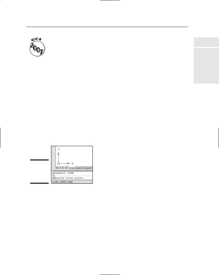
Keeping with the space theme, you can think of the model and paper spaces as parallel universes. We tell you a lot more about these two spaces in Chapter 5. At this time, you just need to recognize this part of the screen. The double-headed arrow figure at the lower-left corner of the screen (see Figure 2-7) is called the UCS icon. When it looks like this, you’re in model space. And that’s where you should be when you’re drawing your buildings, valves, or bridges.
Figure 2-7:
The model space UCS icon.
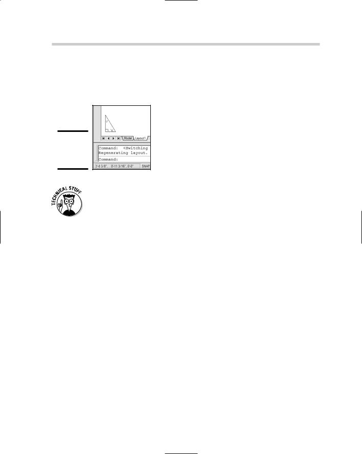
If your UCS icon looks like the one in Figure 2-8, you’re in the other space — paper space. This is where you put your drawing’s title block and add notes and such. If your screen looks like Figure 2-8 instead of Figure 2-7, click the tab that says Model at the bottom left of the drawing area to switch to model space.
Crosshairs
Book I
Chapter 2
the NavigatingInterface AutoCAD
The on-screen mouse pointer takes on at least two different appearances when you’re working in AutoCAD. When you move the mouse outside the drawing area, it looks like the standard arrow pointer you see everywhere
26 Touring the AutoCAD Interface
else in Windows. When you’re inside the drawing area, it turns into a pair of lines that intersect at right angles, with a small square box (called the pickbox) where they cross. You can change the length of the crosshairs in the Options dialog box.
Figure 2-8:
The paper space UCS icon.
You also see the pickbox — without the crosshairs — when you’re selecting objects. Many users find the default size (3 pixels square) too small, and we concur. To change the size of the pickbox, type PICKBOX, press Enter, and then set a new value. We find a 5-pixel-square pickbox a good compromise.
The floating command window
The command line — also known as the command prompt — is one of the things that makes AutoCAD AutoCAD. It’s a throwback to earlier days, before dialog boxes, toolbars, and pull-down menus were a glint in Bill Gates’s eye. The command line lives inside the command window, that area of text near the bottom of your screen.
AutoCAD is one of the few graphics programs where you still type. Not just numbers and distances, but actual command names and options. Unlikely as it may seem (but obvious to grizzled AutoCAD old-timers), communicating with AutoCAD through the keyboard is one of the more efficient ways of using the program.
When you’re new to AutoCAD, though, it’s not an obvious thing to remember. That’s why most CAD classrooms have a sign in big red letters that says Watch the command line! AutoCAD 2006 made a slight lurch into the twentyfirst century with something called dynamic input. When enabled, AutoCAD displays interactive tooltips near the cursor; these show you a lot — but not all — of the command line information. You may still need to look down at the bottom of the screen to get the whole story. And if you’re using AutoCAD 2005 or an earlier version, WATCH THE COMMAND LINE!
Touring the AutoCAD Interface |
27 |
In AutoCAD 2006 and later you can turn the command window off and on with the Ctrl+9 toggle. We’ve even seen books that recommend that you turn it off, but we think this is a bad idea. The dynamic input tooltips do not show you everything that the command window does, so even if you’re using AutoCAD 2006 or later, and at the risk of repeating ourselves . . . watch the command line!
We tell you a bit more about the command window a couple of paragraphs from here. So you can stop watching it until then.
The status bar
At the bottom of the application window is the status bar. The status bar contains three elements. At the left side is the coordinates display, which shows the x-, y-, and z-values of wherever your crosshairs happen to be at a given moment. By default, the coordinates constantly update as you move your mouse around. Also by default, the coordinate values display as decimal numbers with four places of precision. If you change to a different type drawing unit (we describe units in Chapter 5 of this minibook), the format of the coordinates changes to match the new unit’s type.
To the right of the coordinates readout is a set of buttons where you can easily toggle a range of drafting modes such as snap, grid, object snap, and so on. We tell you more about these modes in Chapter 6 of this minibook.
Finally, at the right end of the status bar, comes the status bar tray. You should see anywhere from three to eight icons here; their functions are listed in Table 2-1.
|
Table 2-1 |
Status Bar Tray Icons |
||
|
Button |
Function |
Description |
|
|
|
|
|
|
|
|
|
Communication Center |
Connects to Autodesk’s Web site |
|
|
|
||
|
|
|
|
and shows articles, tips, and |
|
|
|
|
software updates. |
|
|
|
|
|
|
|
|
|
|
|
|
|
Lock/Unlock toolbars/windows |
Allows or prevents moving tool- |
|
|
|
||
|
|
|
|
bars, palettes, and command |
|
|
|
|
window. |
|
|
|
|
|
|
|
|
Associated standards file |
Visible if CAD standards checking |
|
|
|
||
|
|
|
|
is enabled; compare drawing prop- |
|
|
|
|
erties (such as layer names, styles, |
|
|
|
|
|
|
|
|
|
and so on) with associated draw- |
|
|
|
|
ing standards file. We discuss |
|
|
|
|
standards checking in Book VIII. |
|
|
|
|
|
Book I
Chapter 2
the NavigatingInterface AutoCAD
(continued)
28 |
Communicating with Your Software |
|
||||
|
|
|
|
|
|
|
|
|
|
|
|
|
|
|
|
|
Table 2-1 (continued) |
|
||
|
|
|
|
|
|
|
|
|
|
Button |
Function |
Description |
|
|
|
|
|
|
|
|
|
|
|
|
|
Manage xrefs |
Visible if external reference draw- |
|
|
|
|
|
||
|
|
|
|
|
|
ings are attached to a current |
|
|
|
|
|
|
drawing, and indicates if xrefs |
|
|
|
|
|
|
|
|
|
|
|
|
|
need updating. We tell all about |
|
|
|
|
|
|
xrefs in Book VI. |
|
|
|
|
|
|
|
|
|
|
|
|
Plot/Publish |
Signals the end of the plot or pub- |
|
|
|
|
|
||
|
|
|
|
|
|
lish job and indicates errors (if |
|
|
|
|
|
|
any). |
|
|
|
|
|
|
|
|
|
|
|
|
|
|
|
|
|
|
|
Performance Tuning |
Changes the way your computer |
|
|
|
|
|
||
|
|
|
|
|
|
performs when working in the 3D |
|
|
|
|
|
|
environment. |
|
|
|
|
|
|
|
|
|
|
|
|
|
|
|
|
|
|
|
Clean Screen |
Toggles the Clean screen func- |
|
|
|
|
|
||
|
|
|
|
|
|
tionality as shown earlier. |
|
|
|
|
|
|
|
|
|
|
|
|
|
|
|
|
|
|
|
Trusted Autodesk DWG |
Displays DWG files that were |
|
|
|
|
|
||
|
|
|
|
|
|
created by an Autodesk product |
|
|
|
|
|
|
or licensed real DWG. |
|
|
|
|
|
|
|
|
|
|
|
|
|
|
You will see the Performance Tuning icon (the wrench) only from the time you first open AutoCAD 2007 until the first time you look at the Performance Tuning Log by clicking the icon. It will reappear if either Performance Tuning or the Communication Center needs to alert you of an update.
Communicating with Your Software
So now you know what everything is . . . but what do you do with it? You saw at the beginning of this chapter that there are a few ways to start AutoCAD. Now you’re about to discover that you can do just about anything in multiple ways in AutoCAD, beginning with how you speak AutoCADese.
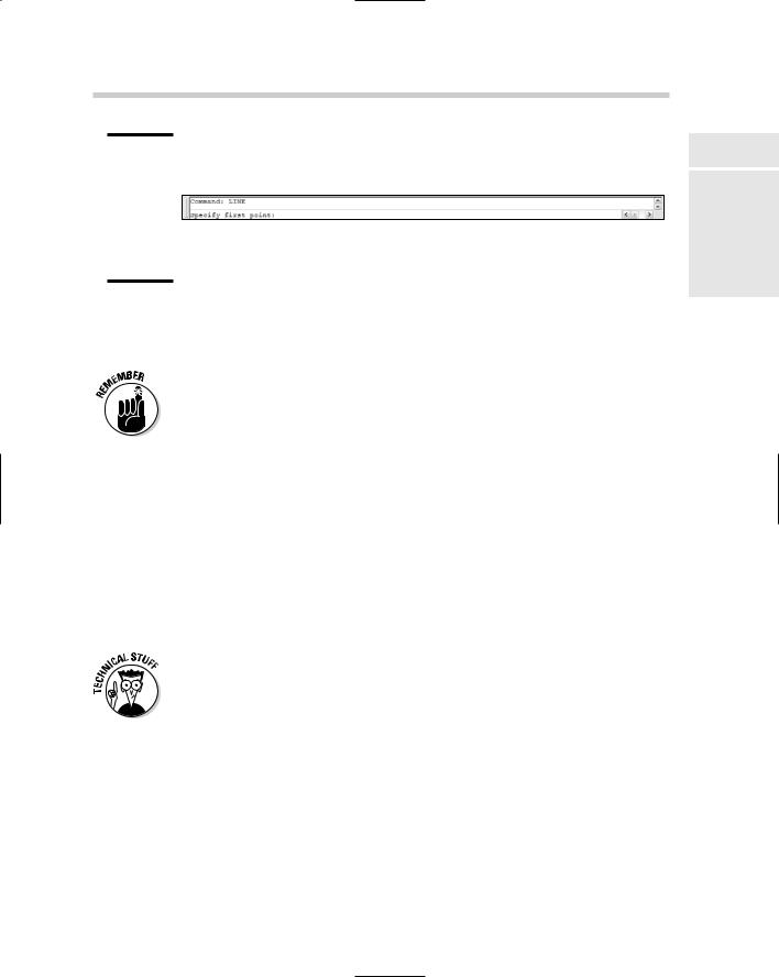
The command line
Not to be confused with the LINE command, the command line is the place where AutoCAD talks back to you (see Figure 2-9). Sometimes it just echoes what you type (it’s easy to assume that it’s not very bright), but more often it engages you in a helpful — if occasionally cryptic — dialog box.
Typically, you start your conversation with AutoCAD by issuing a command. If you want to draw something new, AutoCAD usually starts by asking where you’d like it to start. You pick a point, and then AutoCAD asks how big you want it. You tell AutoCAD, and the program draws the object.
Communicating with Your Software |
29 |
Figure 2-9:
The LINE command on the command line in the command window.
If you want to edit something that’s already there, you issue a command — for example, MOVE. AutoCAD asks you to select the objects to move. You select them and press Enter to confirm your selection. The command now starts prompting — for example, the MOVE command prompts for a base point (a from point) and a second point (a to point).
You can switch off the display of the command window, but we think that’s a bad idea. There’s just not enough feedback from dynamic input on its own.
Dynamic input
Not that we’re badmouthing dynamic input. In fact, it’s a great addition to AutoCAD, but it is one of those things that will probably be easier for the newbies to adjust to than it will for the old-timers.
When dynamic input is enabled (by choosing the DYN button on the status bar), AutoCAD displays tooltips near the crosshairs whenever a command is active. When AutoCAD is expecting you to pick a point, the tooltip displays a constantly updating coordinate readout (x- and y-coordinates only). If AutoCAD needs more information, for example, the radius of a circle, you can type the numbers into the tooltip.
Dynamic input mode is highly configurable. Right-click over the DYN button and choose Settings to display the Dynamic Input tab of the Drafting Settings dialog box. You can turn options off and on here and further refine them by clicking the Settings buttons under Enable Pointer Input and Enable Dimension Input.
Dialog boxes
AutoCAD has two different types of dialog boxes — modal and modeless. Modal dialog boxes are the regular, old dialogs you see in every Windows program. They pop up whenever you save an unnamed drawing, or want to format your units, or make some drawing settings. Modal dialog boxes like Save, Open, Plot, and so on, take command of AutoCAD. You can’t do anything else while one of these dialog boxes is open.
Book I
Chapter 2
the NavigatingInterface AutoCAD
30 Running AutoCAD Commands
Modeless dialogs can stay open while you do other things in AutoCAD. They’re so unique, in fact, that they’re not even called dialog boxes. They’re called palettes, and you’ve already learned a thing or two about them. There are a half-dozen and more modeless dialog boxes — or palettes — in AutoCAD, and we’ll highlight their importance at appropriate places in the text.
Running AutoCAD Commands
Even when you use the menus or toolbars to execute commands, there are still significant differences between AutoCAD and other Windows applications that you might be familiar with.
Grasping the AutoCAD Difference
The fundamental difference with AutoCAD is that AutoCAD expects you to take part in a conversation. When you tell the program you want to move something, AutoCAD asks what do you want to move, where do you want to move it from, and where do you want to move it to?
Most of this conversation takes place in dialog boxes and the dynamic input tooltip. We can’t give you a standard format for this dialog. One of the delights of AutoCAD is the number of different ways the program has of doing what you ask it to do. All we can do at this point is refer you to the chapters to come (starting with the early chapters of Book II).
Repeating a command
Oftentimes in AutoCAD, you want to perform the same action on different objects. You might, for example, want to move a bunch of linework to a different layer, and then move a bunch of text to a third layer.
Pressing Enter or pressing the spacebar at a blank command prompt repeats the last command. You can also right-click and choose the last command from the top of the shortcut menu.
A nifty feature was added to AutoCAD 2004’s Options dialog box, and you can use it in any 2004 or later version of AutoCAD or AutoCAD LT. On the User Preferences tab, Windows Standard Behavior area, click the Right-Click Customization button. In the dialog box, check the Turn on Time-Sensitive Right Click box. Click Apply and Close, and then click OK. Now, if you rightclick within a quarter-second (the default value in the dialog box), you get a carriage return, just as if you’d hit the Enter key or spacebar. If you keep the

Grasping the AutoCAD Difference |
31 |
right mouse button pressed down for longer than a quarter-second, then you get whatever Windows shortcut menu is appropriate to the current command.
Canceling a running command
To cancel a command, simply press Esc. If you’re a long-time user of AutoCAD, and have been away for . . . well, a long time, you may be used to the Ctrl+C combination that issued a Cancel in all DOS versions of AutoCAD. If you’re not one of those grizzled old-timers, you know very well that Ctrl+C copies selected objects to the Windows Clipboard. Whatever your origins, remember that Esc cancels whatever’s going on at present.
Invoking transparent commands
Most AutoCAD commands are meant to be run without interruption. You wouldn’t, for example, start drawing a line and then decide in the middle of the line sequence that you wanted to draw a circle. Well, maybe you would, but trust us, it’s not very efficient.
There are other times, however, when it is efficient to run one command inside another. For example, you might be placing a very long linear dimension, and you’d like to be able to zoom in closely on one end of the object to be dimensioned, and then zoom in closely again on the other end.
You can do this with AutoCAD’s display commands, as well as some of the drafting settings, because these commands can be run transparently. A
transparent command is one that can be executed in the middle of another command.
You may, for example, be in the middle of creating a linear dimension. You realize you’re zoomed too far out to be able to pick the defining points accurately, so you go to the Standard toolbar and pick one of the Zoom commands. You execute your zoom, and when you’re done, AutoCAD takes you back to the command you were running. Same thing happens with toolbars — just click a tool button, and your top-level command is suspended while the secondary command executes.
You can mimic this behavior at the command prompt by typing an asterisk before the command. The asterisk is a sign to AutoCAD that what follows is to be executed transparently. Of course, not all commands can be run transparently, but many can, including most of the display commands. Go ahead and experiment: Just type an asterisk, and then a command, and see what happens.
Book I
Chapter 2
the NavigatingInterface AutoCAD