Добавил:
Опубликованный материал нарушает ваши авторские права? Сообщите нам.
Вуз: Предмет: Файл:

AutoCAD & AutoCAD LT All-In-One Desk Reference For Dummies (2006)

.pdf
Скачиваний:
90
Добавлен:
17.08.2013
Размер:
17.7 Mб
Скачать

542 Protecting Your Drawings

11.On the Enrollment page, enter all the required information and click Accept.

After you submit the information, you’ll receive an e-mail explaining how to obtain the new digital signature. Follow the information in the e-mail to finish the process.

Digitally signing a drawing file

The following procedure explains how to digitally sign a drawing file. It assumes that you have already obtained a digital signature from a vendor of your choice or from VeriSign, as explained in the preceding steps.

1.Choose File Save As.

The Save Drawing As dialog box is displayed.

2.In the Save Drawing As dialog box, choose Tools Security Options.

The Security Options dialog box is displayed and contains different options for working with passwords and digital signatures.

3.In the Security Options dialog box, click the Digital Signature tab.

The Digital Signature tab (see Figure 3-14) displays the different digital signatures found on the computer and some options.

Figure 3-14:

No ink is required for using digital signatures.

4.On the Digital Signature tab, select the Attach Digital Signature After Saving Drawing check box.

After you select this option, other controls on the tab become enabled.

5.Select a digital ID from the Select a Digital ID (Certificate) area.

The first digital ID in the list is selected by default; if you have more than one digital ID, you need to specify which one you want to use.

Protecting Your Drawings 543

6.Optionally, you can specify a time stamp from the Get Time Stamp From drop-down list box, which we recommend doing.

The time stamp helps to validate the digital signature.

7.Optionally, you can add comments for the individual who will be opening or viewing the file later.

For example, you might want to add a comment about whether the file has been approved for manufacturing.

8.Click OK.

The Security Options dialog box closes and you are returned to the Save Drawing As dialog box.

9.Finish specifying the filename and location for the drawing you are saving and click Save.

The Save Drawing As dialog box closes and the drawing is saved with a digital signature. You know that the drawing has been signed when the Validate Digital Signatures icon (see Figure 3-15) appears in the status bar.

Figure 3-15:

Success! The drawing has been digitally signed.

Opening a digitally signed drawing file

Digitally signed drawings serve a different purpose than a drawing you might be creating or editing. This is why they are displayed in a slightly different way in Windows Explorer. The icon for a digitally signed drawing file includes two red and yellow marks (okay, we know you can only see them in black and white in this book) in the upper-right corner (see Figure 3-16).

The following procedure explains how to open a drawing that has been saved with a digital signature:

1.Choose File Open.

The Select File dialog box is displayed.

2.In the Select File dialog box, browse and select the file you want to open.

Book VIII

Chapter 3

with WorkingFiles Drawing

544 Protecting Your Drawings
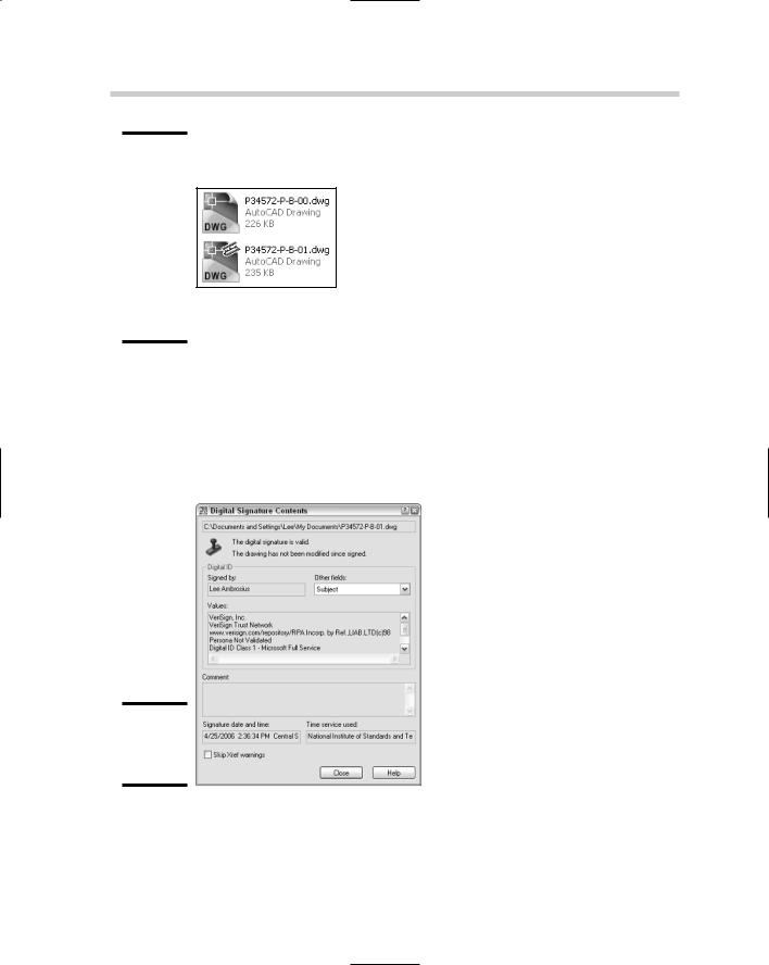
Figure 3-16:

The top icon is displayed for a drawing file; the bottom icon is displayed for a digitally signed drawing file.

The selected file should be highlighted in the dialog box and its name displayed in the File Name text field.

3.Click Open.

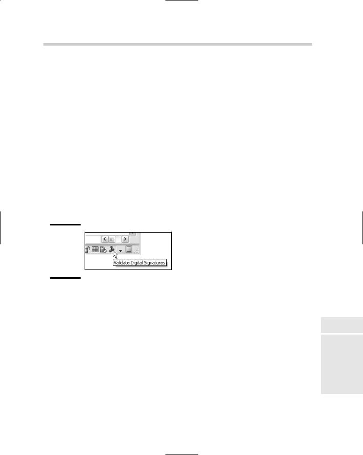
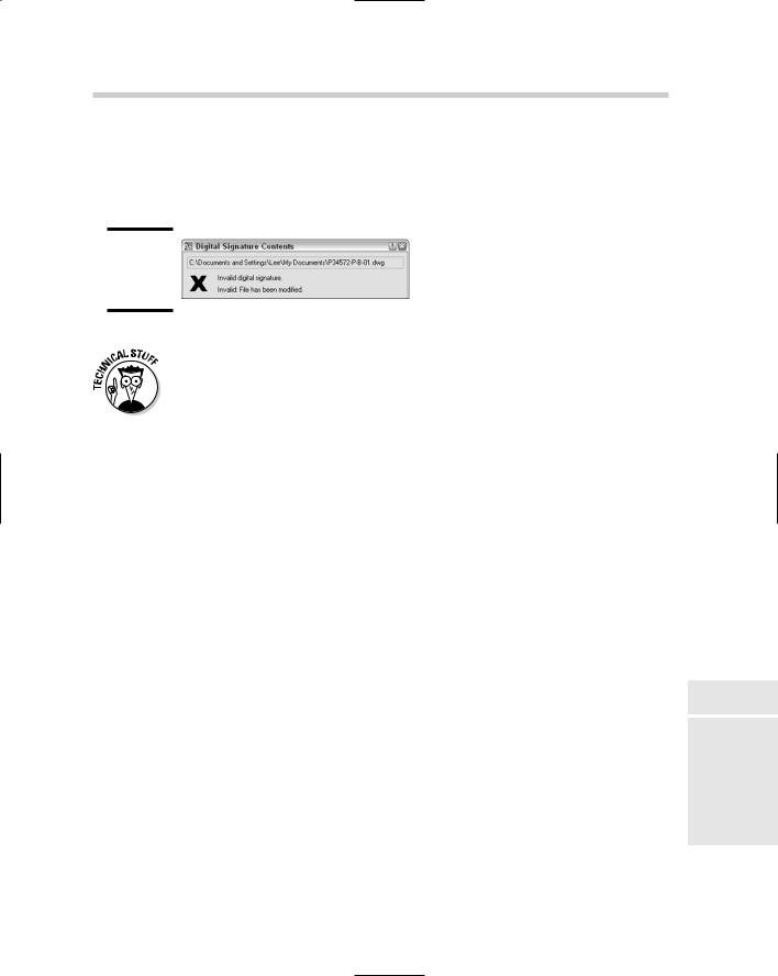
The Select File dialog box closes and the Digital Signature Contents dialog box is displayed (see Figure 3-17).

Figure 3-17:

Digital signature information.

4.In the Digital Signature Contents dialog box, review the information to make sure everything is correct; then click Close.

Protecting Your Drawings 545

The Digital Signature Contents dialog box closes and the Validate Digital Signatures icon is displayed in the status bar. If the digital signature is invalid, you see a warning notification at the top of the Digital Signature Contents dialog box (see Figure 3-18).

Figure 3-18:

When digital signatures go bad.

You can control the display of the Digital Signature Contents dialog box with the system variable SIGWARN. Enter SIGWARN at the command prompt to change its current value. A value of 0 suppresses the display of the dialog box unless the digital signature is invalid. A value of 1 displays the dialog box. (This is the default behavior.)

Digitally signing a batch of drawings

If you have a large set of drawing files that need to be digitally signed all at once, Autodesk offers an external utility to do so. This utility is properly named Attach Digital Signatures. It’s pretty basic and easy to understand. The following procedure explains how to access and digitally sign multiple drawing files at one time:

1.Click Start [All] Programs Autodesk AutoCAD 2007 Attach Digital

Signatures.

The Attach Digital Signatures dialog box (see Figure 3-19) is displayed.

2.In the Attach Digital Signatures dialog box, click Add Files.

The Select File dialog box is displayed.

3.In the Select File dialog box, browse and select the drawing files that you want to digitally sign.

The selected files are highlighted and each name is displayed in the File Name text field.

4.Click Open.

The Select File dialog box closes and you are returned to the Attach Digital Signatures dialog box. The names of the selected files are added to the list box.

5.Specify the digital ID, time stamp, and comments as desired.

Book VIII

Chapter 3

with WorkingFiles Drawing

546 Protecting Your Drawings
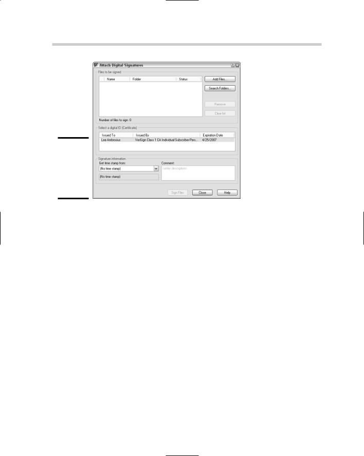
Figure 3-19:

Attaching digital signatures to multiple drawing files.

6.Click Sign Files.

The process of signing the files begins. When it is completed, you are given a summary of the number of files that were signed.

7.On the Signing Complete message box, click OK.

This closes the message box that tells you the number of files signed.

8.In the Attach Digital Signatures dialog box, click Close.

The Attach Digital Signatures dialog box closes.

Chapter 4: Sharing Electronic Files

In This Chapter

Sharing drawings with non-AutoCAD–based products

Taking drawings to the Internet

Emulating paper digitally

Working with the Design Web Format (DWF)

Drawing files are one of the by-products of using AutoCAD. The electronic version of a drawing is much more important than the paper

copy that is produced when you use the PLOT and PUBLISH commands. To deliver a set of drawings efficiently to a client or someone else, the drawings must remain as digital data. This doesn’t mean that a hard copy of the drawing file isn’t important; it is just slower to deliver and changes can’t be communicated in an ideal way.

This chapter focuses on delivering a representation of a drawing file in a digital format that can’t be modified; well, the original drawing isn’t affected. Sharing drawing files can be challenging; others want your drawing files, but they may not be able to view or use them with their software application of choice. AutoCAD offers a few solutions to help share drawing files with people who don’t own a CAD program or people who do own a CAD program but use something other than AutoCAD.

AutoCAD also offers a variety of options for accessing FTP sites, project management sites developed by Autodesk to work with their products such as Buzzsaw and Streamline, and publishing drawing files to Web sites.

Sharing Drawings with Non-AutoCAD–based Products

When you work with CAD, you often need to share your drawing files with others. However, not everyone’s CAD application is the same. For this reason, CAD applications must be able to communicate in other file formats. AutoCAD provides various different output file formats so that it can more easily exchange drawing files with other programs. You may be familiar with some of these file formats, and others you may not be.

548 Taking Drawings to the Internet

You can use three commands to export to a different file type: SAVEAS, EXPORT, and PLOT. Other commands are available, such as BMPOUT, PNGOUT, JPGOUT, and TIFOUT, that you can use to export objects in a drawing to a raster image file. Here are the listed file formats that can be exported out of AutoCAD.

DXF. Drawing Interchange Format

WMF. Microsoft Windows Metafile

ACIS. ACIS solid object file

STL. Solid object stereolithography file

EPS. Encapsulated Postscript file

DXX. Attribute extract DXF file

BMP. Windows Bitmap file

JPG. JPEG graphic file

PNG. Portable Network Graphics file

TIF. Tag Image File Format

3D DWF. 3D Autodesk Design Web Format

DWF. Design Web Format

PDF. Adobe Acrobat Portable Document File

PLT. AutoCAD Plot file

AutoCAD LT does not support the file formats of ACIS, STL, EPS, DXX, or 3D DWF.

Taking Drawings to the Internet

AutoCAD can and does play a role in being able to connect to the Internet to access drawings that have been posted for you to reference, or to be able to push content to a Web site. All of AutoCAD’s primary file access commands are capable of utilizing FTP — File Transfer Protocol. This allows you to access and place files on a remote server that could be just around the

block or halfway around the world. For the most part, the location of the FTP site is transparent to you because it is integrated into AutoCAD.

Autodesk offers two project collaboration sites that users of their products can sign up to use for a fee. The project collaboration sites are similar to FTP sites and how they are integrated into AutoCAD and other Autodesk

Taking Drawings to the Internet 549

products, but they offer much more than just a place to park drawing files. These sites allow for history tracking when files change, embedded file viewers, permissions-based access, and a built-in notification system, to just name a few bullet points of these services.

Project collaboration sites are great, but sometimes they are overly based on the type of information you need to share across the Internet. Autodesk does offer publishing tools that can take a set of drawing files and publish them to Web-friendly formats, such as DWF, JPG, and PNG. This feature is rather basic in its abilities, but if you are not familiar with Web page design, they are great for putting together a nice little interface for your clients to access drawings and information from.

Using an FTP site

Working with an FTP site from inside AutoCAD is similar to accessing an FTP site through Internet Explorer. Both require the location, a user name, and password. The only difference is that you can open and save to the FTP site right from AutoCAD instead of downloading the files first and then later reuploading them.

Virtually every file navigation dialog box inside AutoCAD can access an FTP site. One of the nice things is that it allows you to configure the FTP site as a reusable location. So if you happen to be working on a project over a period of time, you won’t have to worry about forgetting the address, user name, or password but rather just need to set it up once and it is there until you remove it.

The following procedure uses the File menu to start the OPEN command and configure and use an FTP location from inside AutoCAD.

1.From the File menu, choose Open.

The Select File dialog box appears.

2.In the Select File dialog box, choose Tools Add/Modify FTP

Locations.

The Add/Modify FTP Locations dialog box appears (see Figure 4-1).

3.In the Add/Modify FTP Location dialog box, enter the location in the Name of FTP site.

Even though the text field is called Name of FTP site, it is actually the URL for the FTP location. A sample URL is ftp.websitename.com/drawings.

4.Select the logon type under the Log On As area of either Anonymous or User.

Book VIII

Chapter 4

SharingElectronic

Files

550 Taking Drawings to the Internet
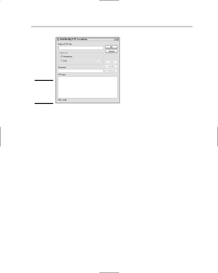
Figure 4-1:

Establishing an FTP location.

If you specify User, you must enter the user name that has been set up for you to access the FTP site. If no user name and password are required, you can use Anonymous.

5.Enter the password that is associated with the user name if one exists in the Password text field.

As the password is entered, it is automatically masked so that the actual values of the keys pressed do not appear on-screen.

6.Click Add.

An entry for the FTP location is added to the list box at the bottom of the dialog box. You can later select the FTP location from the list box and click Modify or Remove to make changes to it.

7.Click OK.

The Add/Modify FTP Location dialog box closes and you are returned to the Select File dialog box.

8.In the Select File dialog box, click FTP in the shortcuts pane on the left side.

The Select File dialog box updates and displays an FTP Locations item which contains the FTP locations that have been defined.

9.Finish specifying the file name and location for the drawing you are looking to open, and click Open.

The Select File dialog box closes and the drawing is opened in the drawing editor. Don’t forget that you can access the FTP location from most file navigation dialog boxes from inside AutoCAD.

Taking Drawings to the Internet 551

Publishing drawings to the Web

One of the great things about AutoCAD is its robust set of features that doesn’t just focus on drafting-based features but contains tools for presenting design concepts across the Internet. One of these presentation tools helps to deliver drawing files to the Web through a wizard. This wizard allows you to specify some basic Web template designs, the visual output for the drawing files specified, and different layouts in drawing files. Autodesk calls this feature Publish to Web.

AutoCAD LT does not support the feature Publish to Web.

The Publish to Web feature is not meant to be a one-size-fits-all type of feature; it is designed for people not familiar with HTML and Web page design. If you are familiar with HTML and creating Web pages, you may find that the implementation is limiting, but if you don’t know how to create Web pages, you may find it purely magical. The feature does offer some nice capabilities for dragging and dropping from the images on the Web pages with i-drop to being able to quickly modify an existing set of drawings that might have been changed by editing the Publish to Web file that it creates. See the sidebar, “Autodesk i-drop,” for information on i-drop.

Drawing files can be published to Web pages by using the PUBLISHTOWEB command. You can start this command in a number of ways:

File menu. Choose File Publish to Web.

Keyboard input. Type PUBLISHTOWEB and press Enter.

Command alias. Type PTW and press Enter.

Use any of the three methods to initiate the PUBLISHTOWEB command. The following procedure uses the File menu to start the PUBLISHTOWEB command and creates a simple Publish to Web project.

1.The Publish to Web feature can’t be used on drawings that are not first saved, so save the current drawing before continuing on.

2.Use one of the previously described methods to initiate the PUBLISHTOWEB command.

The Publish to Web dialog box appears (see Figure 4-2).

3.In the Publish to Web dialog box, select Create New Web Page and click Next.

The option is pretty self explanatory. If you select Edit Existing Web Page, you are prompted to select an existing file with the extension PTW that was created previously with the Publish to Web feature. After you specify the file, you can edit the page title and description.

Book VIII

Chapter 4

SharingElectronic

Files