Добавил:
Опубликованный материал нарушает ваши авторские права? Сообщите нам.
Вуз: Предмет: Файл:

AutoCAD & AutoCAD LT All-In-One Desk Reference For Dummies (2006)

.pdf
Скачиваний:
90
Добавлен:
17.08.2013
Размер:
17.7 Mб
Скачать

522 Using AutoCAD’s CAD Standards Tools

15.In the Layer Translator dialog box, click Translate.

The Layer Translator dialog box closes and the layers are updated based on the specified layer translations.

Batch checking drawings

Both standards tools discussed up to this point must be set up and run drawing by drawing. This isn’t a very efficient process if you have hundreds of drawings for a single project. Wouldn’t it be nice if a utility could check a large number of drawings at once so you don’t have to go through each drawing one by one?

You’re in luck! An external utility called the Batch Standards Checker allows you to take a number of drawings and check them for standards violations. The Batch Standards Checker is very similar to the Configure Standards dialog box in how some of the tabs work. One of the downsides to the Batch Standards Checker is that it can’t fix any problems it finds; it is only designed to check for violations, but it is still much faster than checking each file individually.

The following procedure uses the Batch Standards Checker to check drawing files for any standards violations:

1.Click the Start button [All] Programs Autodesk AutoCAD 2007

Batch Standards Checker.

The Batch Standards Checker (see Figure 2-11) application is displayed.

Figure 2-11:

Checking standards for more than one drawing at a time.

Using AutoCAD’s CAD Standards Tools 523

2.In the Batch Standards Checker, click the Drawings tab.

The Drawings tab allows you to specify which drawing and drawing template files that you want to check for standards violations in.

3.Click the + (plus sign) button to add drawing or drawing template files to the list for processing.

The Batch Standards Checker – File Open dialog box is displayed and allows you to select multiple drawing and drawing template files.

4.In the Batch Standards Checker – File Open dialog box, browse and select the files that you want to check for standards violations.

The name of each selected file is added to the File Name text field.

5.Click Open.

The selected files are added to the Drawings to Check list. You can view some of the properties of the files in the Description area on the right side of the dialog box. You can change the order in which files are processed or remove then from the list altogether using the buttons

in the middle of the dialog box.

6.Optionally, click Check External References of Listed Drawings.

When the check box has a check mark, each drawing is checked for external references. If a drawing contains external references, those files are also checked to make sure they don’t contain any standards violations.

7.Click the Standards tab.

The Standards tab (see Figure 2-12) allows you to specify which drawing standards files should be used to check for standards violations.

8.Select one of the top two options to control which drawing standards files are used to check the selected drawing files.

9.The top option, Check Each Drawing Using Its Associated Standards

Files, is useful if each drawing on the Drawings tab has at least one associated drawing standards file. If not, use the Check All Drawings Using the Following Standards Files option.

10.If Check All Drawings Using the Following Standards Files is selected, click the + (plus sign) button to add drawing standards files to the list for processing.

The Batch Standards Checker – File Open dialog box is displayed and allows you to select multiple drawing standards files.

Book VIII

Chapter 2

Standards CAD

524 Using AutoCAD’s CAD Standards Tools

Figure 2-12:

The Standards tab should look similar to the Configure Standards dialog box.

11.In the Batch Standards Checker – File Open dialog box, browse and select the drawing standards files you want to use.

The name of each selected file is added to the File Name text field.

12.Click Open.

The selected files are added to the Standards Used for Checking All Drawings list. You can view some of the properties of the files in the Description area on the right side of the dialog box. You can change the order in which files are processed or remove them from the list altogether using the buttons in the middle of the dialog box.

13.Click the Plug-Ins tab.

The Plug-Ins tab (see Figure 2-13) allows you to specify which plug-ins are used when checking the specified drawings against the selected drawings standards files.

14.Check or uncheck the plug-ins that you want to use for checking standards against the specified drawing files.

The same plug-ins are available here that are available in the Configure Standards dialog box of the STANDARDS command.

15.Click the Notes tab.

The Notes tab allows you to provide a description for the standards check file, just in case the file is needed at a later date to reprocess the same drawing files after they have been revised.

Using AutoCAD’s CAD Standards Tools 525

Figure 2-13:

Controlling which plugins are used.

16.Enter any type of textual note that you want to in the Enter Notes to Be Included in the Report text box.

17.From the File menu, choose Save Check File.

The Batch Standards Checker – File Save dialog box is displayed.

18.In the Batch Standards Checker – File Save dialog box, browse to a location and enter a name for the Standards Check (CHX) file.

19.Click Save.

The Standards Check file is created in the specified location with the provided name. The Standards Check file contains information about which drawings are to be processed, the drawing standards files to use, and the other options you have specified up to this point.

20.From the Check menu, choose Start Check.

The Progress tab is displayed and shows the current progress of the files being checked.

21.When the process is finished, the Standards Audit Report is displayed.

The Standards Audit Report (see Figure 2-14) is displayed in your Internet browser. You can view the different results by clicking the controls located on the left side of the report. The information is stored in the Standards Check file that you saved earlier and can be viewed later by opening the file and choosing View Report from the Check menu.

Book VIII

Chapter 2

Standards CAD

526 Using AutoCAD’s CAD Standards Tools
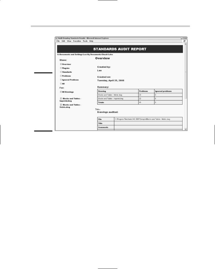
Figure 2-14:

The Standards Audit Report reveals all problems with your standards (well, okay, maybe

not all problems).

Chapter 3: Working with Drawing Files

In This Chapter

File naming standards

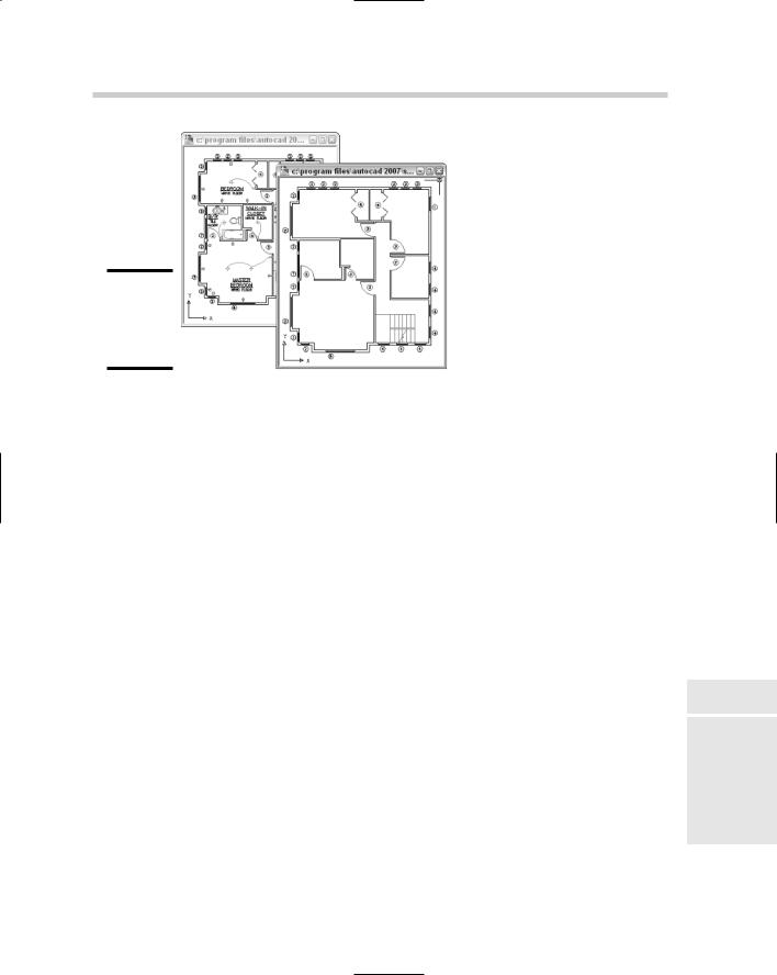
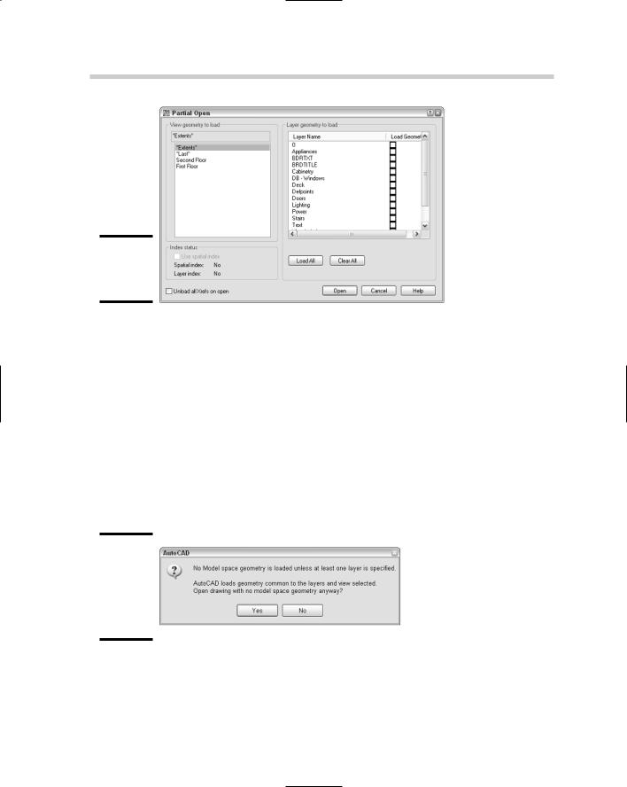
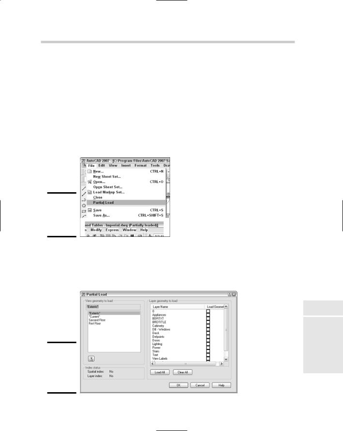
Partially loading a drawing

Controlling what happens during a save

Digitally signing and password-protecting drawings

As you might have noticed, drawing files are the main by-product of using AutoCAD. They are much more important than the paper copy

that is generated when the Plot button is clicked. Paper copies of drawings are designed for presenting a concept or design, but they can’t be modified like the drawing file can. For this reason, you need to take care of your drawing files by storing them in safe locations. You also must ensure that they are properly backed up and must use a logical naming convention so you can later easily find the files.

Many users of AutoCAD don’t fully realize the amount of control they have over their drawing files. This chapter explains some of the different concepts that you might not know about working with drawing files. The concepts we cover range from password-protecting or using digital signatures to protect your drawing files when you share them, to controlling how objects and layers are indexed to make loading a drawing as an external reference more efficient.

It’s All in the Name: Creating Naming Conventions

Following proper naming conventions is critical to being able to easily find any document, whether it was created with MS Word or AutoCAD. A series of drawing files named Drawing1, Drawing2, and so on won’t be very helpful to you in the future. Instead, you should come up with a meaningful naming convention that tells you at a glance what project a drawing file pertains to. The key to creating a good naming convention is to make sure it is easy to remember and understand. If it is overly complicated, many users tend to do their own thing, making it harder to find files later.

528 Part of a Drawing Can Be a Good Thing: Working with Partial Open

If you are in the architectural field, you might want to include such things as project number, building number, drawing type, and drawing size in your filename conventions. An example of such a filename might be A12345-01- P-D.DWG. This type of convention ensures that files related to the same part of the building and project are grouped together. Of course, good file organization helps to make your projects run more efficiently and effectively, too. Store drawing files in a centralized location so that all drafters who need access to them can get to them. In addition, if you have processes in place to regularly back up all network files, storing them on a network ensures that your drawing files are frequently backed up.

Autodesk first introduced a feature called Sheet Sets with AutoCAD 2005. Many people turned off the feature because they didn’t fully understand the concept. Sheet Sets are great for helping you organize drawings not just by file, but also by directory structure. (Sheet Sets are covered more fully in Book VII, Chapter 2.) Sheet Sets not only provide a way to organize drawings, but they also provide some structure for naming drawings.

AutoCAD 2006 and later versions add support to the Windows search feature for finding text strings located in a drawing file. This can help you find drawing files that might not have been placed in the correct project folder.

Part of a Drawing Can Be a Good Thing:

Working with Partial Open

Part of a drawing as a good thing? You may be thinking that we have slipped off the deep end. You could be right, but hear us out before you jump to any conclusions. We’re referring to a feature called Partial Open, which has been part of the product for the past few releases. This feature allows you to open part of a drawing file into AutoCAD based on a view and selected layers.

AutoCAD LT does not support the Partial Open feature.

Partially opening a drawing file can be a great timesaver when you want to work on a floor plan that contains a lot of annotation, hatches, and dimensions. Instead of waiting for that geometry to load at the beginning of the editing process, you can choose not to load that information until you need to see it. If you happen to need any information in part of the drawing that has not been loaded, you can specify the area of the drawing that you want those objects to be displayed in. The key to being able to take full advantage of this feature is a good set of layer standards and the use of named views. Figure 3-1 shows the same drawing file two different ways: The drawing on the left was opened using Open, and the one on the right was opened using Partial Open.

Part of a Drawing Can Be a Good Thing: Working with Partial Open 529

Figure 3-1:

Using Open versus Partial Open.

A drawing file can be partially opened by using the OPEN or PARTIALOPEN command. You can start these commands in one of two ways:

Keyboard input. Type PARTIALOPEN and press Enter.

Select File dialog box. Start the OPEN command, click the drop-down arrow next to the right of the Open button, and click Partial Open or Partial Open Read-Only.

The following procedure explains how to use the Partial Open feature to load geometry based on a selected view and layers, and how to control the loading of xrefs when a drawing is being partially opened:

1.Use either of the two methods just listed to partially load a drawing file.

Based on the method used, you are prompted to enter the name of the drawing you want to partially open at the command line, the dynamic input tooltip, or in a dialog box. After entering the name of the drawing, the Partial Open dialog box (see Figure 3-2) is displayed. If you selected the Partial Open Read-Only option, the same dialog box is displayed. The only difference is that you won’t be able to edit the drawing and save it back to the file.

2.In the Partial Open dialog box, select a named view under the View Geometry to Load heading.

By default, two named views are available in every drawing file. These are *Extents*, which represents the drawing’s extents (the largest area required to display all objects in a drawing), and *Last*, which represents the view the drawing was saved with.

Book VIII

Chapter 3

with WorkingFiles Drawing

530 Part of a Drawing Can Be a Good Thing: Working with Partial Open

Figure 3-2:

What to partially open . . .

3.Select the Use Spatial Index check box under the Index Status area if it’s available.

Spatial indexing allows for information to be located in a drawing much faster, although it does increase the file size. See “Indexing the content of a drawing” later in this chapter for more information. This option is only available if either spatial or layer indexing was enabled when the file was last saved.

4.In the Layer Geometry to Load area, select the layers that contain the geometry you want to display.

You don’t need to specify any layers, but if you don’t specify at least one, AutoCAD prompts you with a message box (see Figure 3-3). Click No to select some layers before continuing.

Figure 3-3:

AutoCAD’s friendly reminder that you forgot to do something.

5.If the file you are loading contains Xrefs, you can select the Unload All Xrefs on Open check box in the lower-left corner.

Part of a Drawing Can Be a Good Thing: Working with Partial Open 531

Selecting this check box unloads all the Xrefs attached to the drawing. They are not displayed until they are reloaded through the External References palette. This is a great feature if you want to quickly load a drawing that contains a lot of Xrefs and then view only the ones that you are interested in.

6.Click Open to finish the partial open process.

The drawing is partially opened in the drawing editor. You can tell when you are working in a partially opened drawing in two ways: The first is that the Partial Load option is available under the Files menu, and the second is that the text (Partially Loaded) appears after the drawing name in the title bar (see Figure 3-4).

Figure 3-4:

The signs of a partially opened drawing file.

7.If you need to load additional layers, you can use the Partial Load option from the Files menu. This displays the Partial Load dialog box (see Figure 3-5), which is very similar to the Partial Open dialog box.

Figure 3-5:

Loading more layers in a partially opened drawing file.

Book VIII

Chapter 3

with WorkingFiles Drawing