Добавил:
Опубликованный материал нарушает ваши авторские права? Сообщите нам.
Вуз: Предмет: Файл:

AutoCAD & AutoCAD LT All-In-One Desk Reference For Dummies (2006)

.pdf
Скачиваний:
90
Добавлен:
17.08.2013
Размер:
17.7 Mб
Скачать

512 Using AutoCAD’s CAD Standards Tools

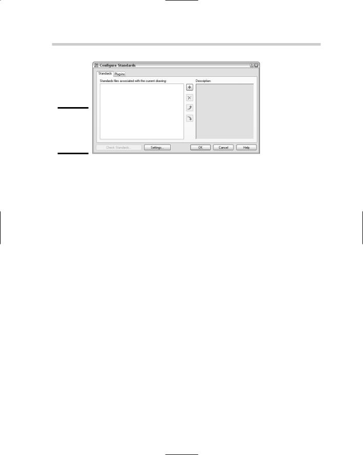
The CAD standards tools provided with AutoCAD help with only a small subset of the items that are part of a good set of CAD standards. Blocks, layouts, page setups, and table styles, for example, are not part of the standards that AutoCAD is designed to manage.

Drawing standards (.DWS) files

A drawing standards file is, for the most part, the same as a drawing or drawing template file, except for its file extension and the type of content that might be saved in it. Here are the most common items found in a drawing standards file:

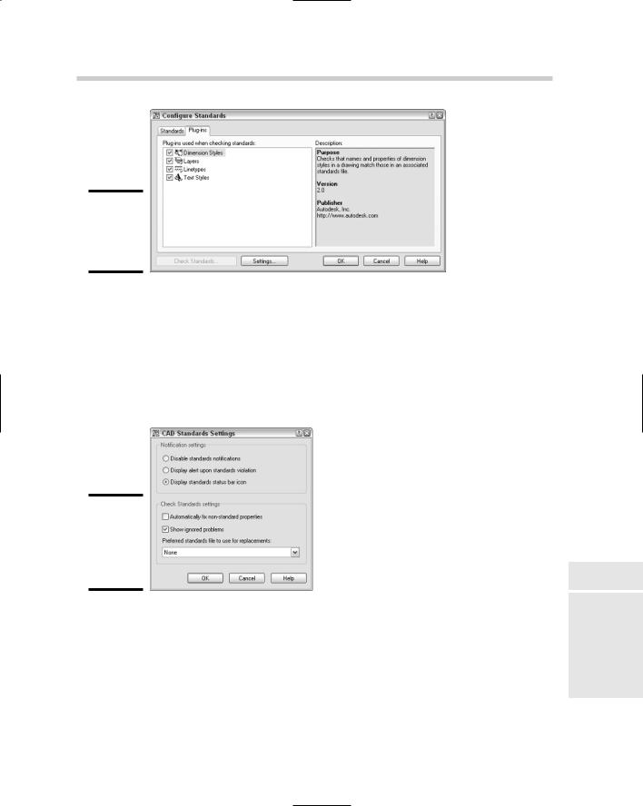
Dimension styles: (Book III, Chapter 2)

Layers: (Book I, Chapter 5)

Linetypes: (Book I, Chapter 5)

Text styles: (Book III, Chapter 1)

The reason for the limited content of drawing standards files is that these types of objects are supported with the built-in CAD standards tools.

The following procedure uses the File menu to start the command and saves the current drawing as a drawing standards file:

1.Create a new drawing based on a drawing template file or from scratch. Add to the drawing any layers, linetypes, dimension styles, or text styles that you want in the drawing standards file.

2.From the File menu, choose Save As.

The Save Drawing As dialog box is displayed.

3.In the Save Drawing As dialog box, select AutoCAD Drawing Standards (*.DWS) from the Files of Type drop-down list.

By default, AutoCAD navigates to the folder of the current drawing file. Storing drawing standards files in a network location so they can be used by others in the office is best.

4.Browse to a different location or use the location that is specified by AutoCAD to save your drawing standards file in.

5.Enter a filename different from the one AutoCAD provides by default.

You might want to name the drawing standards file based on a project name or the type of drawing that the drawing standards file will be used with. For example, you might give the standards file for your elevation drawings the name Elevations, or name the standards file for your plan drawings Plans.

Using AutoCAD’s CAD Standards Tools 513

6.Click Save.

The drawing standards file is created with the specified name and location.

Managing standards

AutoCAD provides a set of tools that allow you to associate a drawing standards file with a drawing and then check that drawing against the associated drawing standards files. This set of tools is known as the Standards Manager and is broken up into two parts: The first is used to configure and associate drawing standards files to a drawing, and the second is used to check for violations in the drawing.

When configuring a drawing to use a drawing standards file, you are specifying which file should be used to check CAD standards against and which plug-ins should be used (essentially, a plug-in is a set of rules used to determine whether there are problems in the drawing). During the checking of the drawing file, you can fix any problems the plug-in finds.

Configuring standards

A drawing standards file can be associated with a drawing using the STANDARDS command. You can start this command in a number of ways:

Tools menu: Select Tools CAD Standards Configure.

CAD Standards toolbar: Click the Configure button on the CAD Standards toolbar.

Keyboard input: Type STANDARDS and press Enter.

Command alias: Type STA and press Enter.

The following procedure starts the STANDARDS command, configures the drawing to use a drawing standards file, and specifies which plug-ins to use:

1.Use any of the four methods just listed to initiate the STANDARDS command.

The Configure Standards dialog box (see Figure 2-1) is displayed.

2.In the Configure Standards dialog box, click the Standards tab.

On the Standards tab, you associate the drawing standards files to be used for the current drawing. If more than one drawing standards file is specified, the order of the files is important. For example, if more than one of the associated drawing standards files has the same name for a layer, the first one encountered from the top of the list is used for validating the standard.

Book VIII

Chapter 2

Standards CAD

514 Using AutoCAD’s CAD Standards Tools

Figure 2-1:

Configuring standards for a drawing.

3.Click the + (plus sign) button located in the middle of the dialog box.

The Select Standards File dialog box is displayed. From this dialog box, you can select which drawing standards files you want to associate with the drawing. Although more than one drawing standards file can be associated with a drawing, only one at a time can be selected from the Select Standards File dialog box.

4.Browse to and select the drawing standards file you want to associate with the drawing.

5.Click Open.

The drawing standards file is added to the list box on the left. When the drawing standards file is selected in the list box on the left, some of the file’s properties are displayed in the list box on the right.

6.Add any additional drawing standards files that you need.

When more than one drawing standards file is associated with a drawing, the Move Up and Move Down buttons are enabled, allowing you to change the order in which the files are used to check for standards violations.

7.Click the Plug-Ins tab.

On the Plug-Ins tab (see Figure 2-2), you can select which plug-ins you want to use for checking the drawing for violations against the associated drawing standards files. AutoCAD comes with a total of four plug-ins — this number hasn’t changed since the feature was first introduced.

8.Select the plug-ins that you want to use when checking for standards violations in the current drawing.

A check mark next to the plug-in means it will be used when checking standards; a plug-in with no check mark means it will not be used.

Using AutoCAD’s CAD Standards Tools 515

Figure 2-2:

Selecting plug-ins for checking standards.

9.Click the Settings button at the bottom of the Configure Standards dialog box.

The CAD Standards Settings (see Figure 2-3) dialog box is displayed. From this dialog box, you can control the display of the notification icon that appears in the status bar when CAD standards are configured, and you can specify how errors are handled during the process of checking for standards violations.

Figure 2-3:

Fine-tuning the behavior of the CAD standards tools.

10.Click OK.

The drawing standards files are associated with the current drawing and the dialog box is closed. By default, a book icon (see Figure 2-4) appears in the status bar denoting that at least one drawing standards file is associated with the drawing.

Book VIII

Chapter 2

Standards CAD

516 Using AutoCAD’s CAD Standards Tools

Figure 2-4:

Icon in the status bar denotes the use of CAD standards.

You can right-click some of the notification icons in the status bar to access specific settings for that feature. For example, if you right-click the book icon used for CAD standards, you can access some of the options for configuring and checking standards.

Checking standards

After a drawing standards file has been associated with a drawing, you can begin to check for standards violations. CAD standards can be checked for a drawing using the CHECKSTANDARDS command. You can start this command in a number of ways:

Tools menu: Select Tools CAD Standards Check.

CAD Standards toolbar: Click the Check tool on the CAD Standards toolbar.

Keyboard input: Type CHECKSTANDARDS and press Enter.

Command alias: Type CHK and press Enter.

The following procedure starts the command and then checks a drawing for violations against the associated drawing standards file and selected plug-ins:

1.Use any of the four methods just listed to initiate the CHECKSTANDARDS command.

The Check Standards dialog box (see Figure 2-5) is displayed. If no standards file has been associated with the drawing file yet, the Associate Standards (see Figure 2-6) message box is displayed. If the message box is displayed, click OK to go to the Configure Standards dialog box.

2.In the Check Standards dialog box, each one of the standards violations is displayed at the top in the Problem area.

The Problem area lets you know what is wrong during the checking process.

Using AutoCAD’s CAD Standards Tools 517

Figure 2-5:

A violation has been detected.

Figure 2-6:

No standards file has been associated with this drawing yet.

3.In the Replace With area, select one of the available fixes.

The Replace With area allows you to designate one of the named objects in the associated standards file that should be used to fix the problem. When the drawing is compared to the standards file, it attempts to locate a recommended fix for you; the recommended fix is designated with a blue check mark next to it in the Replace With area. After an item is selected from the Replace With area, an overview of the changes that will be made is displayed in the Preview of Changes area.

The Preview of Changes area gives you an idea of what is going to happen when the fix is applied. In some cases, a fix can’t be made; for example, if your drawing standards file uses color-dependent plotting whereas the current drawing is name dependent.

Book VIII

Chapter 2

Standards CAD

518 Using AutoCAD’s CAD Standards Tools

4.Click the Fix button to fix the standards violation. If you want to skip a violation, click the Next button and no fix will be made. If you also want to skip the violation the next time the drawing is checked for standards violations, click the Mark This Problem as Ignored check box.

Clicking the Fix button updates the properties of the named object in the drawing so it matches the drawing standards file after you are through checking for standards violations.

5.After all violations have been looked at, the Checking Complete message box is displayed.

The Checking Complete message box (see Figure 2-7) displays a summary of the changes made or not made.

Figure 2-7:

All violations have been evaluated.

6.Click Close.

The Check Standards dialog box closes and the changes to the violations are displayed in the drawing.

Translating layers

The Configure and Check Standards tools are designed to help automate the process of keeping similarly named layers and styles in sync. But what happens if you get a set of drawings from a client or customer and need to make their drawings conform to your layers? You don’t want to have to go through each drawing one by one and map each layer or group of layers to the layer used in your CAD standards.

This is where the Layer Translator comes into play. The Layer Translator allows you to map a single layer or a group of layers to a single layer based on your established CAD standards. After the translation map for layers is set up, you can save the map to a drawing, drawing standards, or drawing template file for use later on additional drawings.

Using AutoCAD’s CAD Standards Tools 519

The Layer Translator is accessed through the LAYTRANS command. You can start this command in several ways:

Tools menu: Select Tools CAD Standards Layer Translator.

CAD Standards toolbar: Click the Layer Translator tool on the CAD Standards toolbar.

Keyboard input: Type LAYTRANS and press Enter.

The following procedure starts the command, creates a layer translation map, and translates the layers in a drawing.

1.Use any of the three methods just listed to initiate the LAYTRANS command.

The Layer Translator dialog box (see Figure 2-8) is displayed.

Figure 2-8:

Translating from one layer to another.

2.In the Layer Translator dialog box, click the New button located below the Translate To area.

The New Layer dialog box (see Figure 2-9) is displayed.

In the New Layer dialog box, you are creating a new layer to be used in the layer translation process from scratch. At minimum, you must specify a name.

3.Modify the properties as necessary for the new layer.

4.Click OK.

The new layer is added to the list under the Translate To area.

Book VIII

Chapter 2

Standards CAD

520 Using AutoCAD’s CAD Standards Tools

Figure 2-9:

Create a new layer to map to.

5.In the Layer Translator dialog box, click the Load button located below the Translate To area.

The Select Drawing File dialog box is displayed and allows you to select a drawing, drawing standards, or drawing template file to load layers from for use in the Translate To list.

In the Select Drawing File dialog box, browse and select an existing file that contains the layers you want to use to create your layer translation from.

6.Click Open.

The layers in the selected file are added to the list in the Translate To area.

7.Click the Map Same button between the Translate From and Translate To areas.

Any layers that have the same name between the two lists will be automatically mapped. This helps speed up the process when creating the translations for a drawing with a larger number of layers.

8.Select the layer or layers from the Translate From area that you want to create a layer translation map for.

The selected layer or layers become highlighted. You can press and hold down the Ctrl key to select multiple layers or the Shift key to select a range of files.

Layers that appear with a white icon next to them in the Translate From area don’t have any objects on them. These layers can be purged from the list and the drawing by right-clicking the list and selecting Purge Layers.

Use the Selection Filter field to quickly select a number of layer names that are similar in name. You can use wildcard characters to help create a complex criterion if needed. For example, you can enter TXT* and click the Select button to highlight all the layers that begin with the letters TXT.

Using AutoCAD’s CAD Standards Tools 521

9.Select the layer from the Translate To area that you want the selected layer or layers in the Translate From area to be translated to.

Layers in both the Translate From and Translate To areas should now be highlighted.

10.Click the Map button to create the layer translation.

The layer translation is added to the Layer Translation Mappings area near the bottom of the dialog box. Each layer that has a translation is removed from the Translate From list to let you know which ones haven’t been mapped yet.

11.Click Settings.

The Settings dialog box (see Figure 2-10) is displayed. The default settings are the best to help maintain good quality CAD standards. The last option in the Settings dialog box is nice so you can see what is on what layer in real-time when a layer or layers are selected from the Translate From list. Only the selected layers are displayed in the drawing.

Figure 2-10:

Taking full control of the translation.

12.In the Settings dialog box, select the desired options and click OK.

The changes to the settings are saved and the Settings dialog box is closed.

13.In the Layer Translator dialog box, click Save.

The Save Layer Mappings dialog box is displayed allowing you to save the layer translations that you have created for re-use.

In the Save Layer Mappings dialog box, browse to the location that you want to export the layer translations to and specify a name for the file. Use the Files of Type drop-down list to create either a drawing or drawing standards file.

14.Click Save.

The file is created in the specified location with the provided name.

Book VIII

Chapter 2

Standards CAD