Добавил:
Опубликованный материал нарушает ваши авторские права? Сообщите нам.
Вуз: Предмет: Файл:

AutoCAD & AutoCAD LT All-In-One Desk Reference For Dummies (2006)

.pdf
Скачиваний:
90
Добавлен:
17.08.2013
Размер:
17.7 Mб
Скачать

502 Managing the Drafting Environment

Training, seminars, and learning material: Sending employees to training or purchasing training materials for them is often hard to justify financially. This is because at times the true return of investment (ROI) is unclear. You must determine as a company how training is conducted when a new release comes out or a new individual is brought onboard.

Managing the Drafting Environment

AutoCAD is a complex drafting program with many different options and support files. Proper management of the AutoCAD environment is not something that just happens overnight. Given the sophisticated drafting environment in AutoCAD, a small group of appointed individuals at your company should be in charge of making updates to support files. Having a small group in charge of updates is especially critical in preventing unauthorized changes that could affect new or existing drawings in a negative way when the files are shared with a large group of drafters. So what is included in the drafting environment?

When we say drafting environment, we’re not talking about background colors and size of the crosshairs — those things don’t affect the final output of a drawing file. Instead, we’re referring to template file locations and where AutoCAD looks for support files such as blocks, fonts, and customization. When you first install AutoCAD, it often looks locally for things such as menu customization, hatch patterns, blocks, fonts, drawing template files, and anything else that is ordinarily shipped with the product. Because AutoCAD doesn’t force specific locations for files, it allows you the flexibility to determine how you want to manage all these support files. The default out-of-the- box locations are local on the computer, but this is not the best way to manage support files.

If a CAD standard changes, you need to update the drawing template files; but if AutoCAD looks locally for these files, updating the files can be a nightmare, depending on how many users you are supporting. Instead of letting all users have their own copies of the drawing template files, place the drawing template files on the network and redirect AutoCAD to look in that location. This way, when a change is made, all the users get the change instantaneously.

All the support paths and folder locations in which AutoCAD looks for the files it needs are defined on the Files tab of the Options dialog box. This means that you can have your drawing template files, plot style files, font files, linetype definition files, and blocks on a network location so you don’t have to worry about any computer using outdated files when changes are made. This also gives you control over who can make changes to these files,

Creating a Good Foundation 503

as opposed to whether they are stored locally on each machine. The other advantage of having these files on the network is that they don’t get lost or forgotten during an upgrade to a newer release.

Creating a Good Foundation

This book is designed to put you on the right path from the start and to help you develop good drafting habits when creating objects like layers, text styles, and blocks. One of the final pieces of the puzzle is how to pull all this information together to start building a good foundation in managing and understanding CAD standards. This isn’t just applicable to CAD managers: Good CAD standards should be practiced by all drafters.

When creating drawings, you often find that you are using the same layers, linetypes, title blocks, and specific styles again and again. As you know, a layer can be added using the Layer Properties Manager, but adding layers manually to each new drawing file can be time-consuming and can introduce errors. This is where the concept of drawing template files comes into play. These files have the file extension .DWT and are located by default under <drive>:\Documents and Settings\<user name>\Local Settings\Application Data\Autodesk\<product>\<release>\<language>\Template. If the concept of templates sounds familiar, it’s because applications that are part of MS Office utilize templates to store formatting and styles that can be reused when creating a new file.

A drawing template is not much different from a drawing file you are used to creating with AutoCAD. The only difference is that you can provide a description for the template that appears when you use the StartUp dialog box. And when you use it to create a new drawing, AutoCAD creates a new unnamed drawing with those styles and features and the default name Drawing1. The numeral at the end of the default name is incremented for each new drawing that is created while the session of AutoCAD is open.

You use a drawing template file to ensure that the styles and formatting are ready to go when you need to create a drawing, and that styles and formatting are consistent among drawings. The most common items included in a drawing template file are

Blocks: (Book VI, Chapter 2)

Dimension styles: (Book III, Chapter 2)

Layers: (Book I, Chapter 5)

Layouts: (Book VII, Chapter 1)

Linetypes: (Book I, Chapter 5)

Materials: (Book V, Chapter 7)

Book VIII

Chapter 1

Management: CADNecessary The

Evil

504 Creating a Good Foundation

Multiline styles: (Book II, Chapter 1)

Page setups: (Book VII, Chapter 1)

Table styles: (Book III, Chapter 1)

Text styles: (Book III, Chapter 1)

UCSs (User Coordinate System): (Book V, Chapter 3)

Viewports: (Book VII, Chapter 1)

Views: (Book II, Chapter 3)

Drawing objects in model and paper space: (Book I, Chapter 5)

Drawing limits and some drafting settings: (Book I, Chapters 5 and 6)

AutoCAD LT does not support the creation or editing of materials used for rendering 3D objects or Multiline styles used to create Multiline objects.

Creating a drawing template file

The following procedure uses the File menu to start the SAVEAS command and creates a drawing template file.

1.Create reusable content in the drawing that you want to have available when you use the template to create a new drawing.

2.From the File menu, choose Save As.

The Save Drawing As dialog box is displayed.

3.In the Save Drawing As dialog box, select AutoCAD Drawing Template (*.DWT) from the Files of Type drop-down list.

By default, AutoCAD navigates to the location that is specified for drawing template files when AutoCAD Drawing Template (*.DWT) is selected from the drop-down list. This location can be changed using the OPTIONS command. We recommend changing where AutoCAD looks for drawing template files to a centralized location, such as a network, to make it easy for multiple users to access the files.

4.Browse to a different location or use the location specified by AutoCAD for saving drawing template files.

5.Enter a different filename other than the one that AutoCAD provides by default.

You might want to add some information to the filename to help identify what the template is used for. For example, you might give your template the name E-Size Lot Plan if you are doing architectural drawings, or B- size Part if you are doing mechanical drawings.

Creating a Good Foundation 505

6.Click Save.

The Template Description dialog box (see Figure 1-1) is displayed and allows you to specify a description and the type of measurement the template should be set to.

Figure 1-1:

The Template Description dialog box.

7.Enter a description of your choice in the Description text field and specify the type of measurement from the Measurement drop-down list.

The description is displayed in the Create New Drawing and Startup dialog boxes. The Measurement option controls which linetype and hatch pattern files are used, along with controlling some settings for inserting blocks into a drawing.

8.Click OK.

The Template Description dialog box closes and the drawing template is saved to the specified location.

The measurement option found in the Template Description dialog box controls a system variable called MEASUREMENT. This variable can be changed at any time by typing MEASUREMENT at the command prompt or dynamic input tooltip, and entering the new value. Use a value of 0 to specify English (Imperial), and 1 to specify Metric.

Using a drawing template file

After you have created a drawing template file, you must understand how to use it to create new drawings. Below are some of the common ways to use a drawing template file to create a new drawing:

NEW command: Start the NEW command and select the drawing template that you want to begin with.

QNEW command: The QNEW command is similar to the NEW command, with one key difference. You can specify a default drawing template file that will be used to create a new drawing when the command is used

Book VIII

Chapter 1

Management: CADNecessary The

Evil

506 Creating a Good Foundation

or each time AutoCAD starts. If no default template file is specified, the QNEW command behaves like the NEW command. To specify the default drawing template file that should be used, start the OPTIONS command and browse to the template that you want to use for the QNEW command under the Template Settings node of the Files tab.

Startup and Create New Drawing dialog boxes: Both the Startup (see Figure 1-2) and Create New Drawing dialog boxes are controlled by a setting in the Options dialog box. These dialog boxes are displayed when AutoCAD first starts up or when the NEW command is started. To control whether these dialog boxes are displayed on system startup, start the OPTIONS command and specify the value Show Startup dialog box from the Startup drop-down list under the General Options section of the System tab.

Figure 1-2:

A different take on startup.

Double-click drawing template file: From Windows Explorer, you can double-click a drawing template file to create a new drawing. If AutoCAD is not running already, it starts, and the new drawing is created.

Specifying a drawing template file for use with QNEW

Often, you find yourself using a specific drawing template repeatedly. The QNEW command was created for this situation. But out of the box, QNEW works just like the NEW command. To make the QNEW command live up to its potential, you need to specify the default drawing template to use through the Options dialog box. This saves you some time because you don’t have to browse and select the drawing template you commonly use for most of the new drawings you create.

The following procedure shows you how to use the Tools menu to start the OPTIONS command and specify a drawing template to use to create a new drawing when the QNEW command is used:

Creating a Good Foundation 507

1.From the Tools menu, choose Options.

The Options dialog box is displayed.

2.In the Options dialog box, click the Files tab along the top of the dialog box.

The Files tab is used to specify things like support folders for AutoCAD to find hatch pattern files or plotter device information.

3.Click the plus sign next to Template Settings to expand it.

The settings related to this group are displayed with additional nodes (see Figure 1-3).

Figure 1-3:

The settings related to template settings.

AutoCAD users see a total of four nodes, whereas AutoCAD LT users see only two. The options Drawing Template File Location and Default Template File Name for QNEW apply to both AutoCAD and AutoCAD LT.

4.Click the plus sign next to Default Template File Name for QNEW.

If no template has been specified, you should see the value None. This designates that QNEW works just like the NEW command does.

5.Select the value of None from under Default Template File Name for QNEW and click Browse.

The Select a File dialog box is displayed and allows you to select a drawing template file.

6.In the Select a File dialog box, specify the drawing template that you want to use when the QNEW command is used.

The selected drawing template file should be highlighted and the name placed in the File Name text field.

7.Click Open.

The Select a File dialog box closes and the value is added under the Default Template File Name for QNEW node.

8.In the Options dialog box, click Apply or OK.

Clicking Apply saves the changes made and keeps the dialog box displayed, whereas clicking OK saves the changes and closes the Options dialog box.

Book VIII

Chapter 1

Management: CADNecessary The

Evil

508 Creating a Good Foundation

Specifying the location of drawing template files

If you create templates for a number of users in your office, you want to be sure they can access them. To make the most of the time you spend creating your own templates, place them in a centralized location and then have AutoCAD look there for them. To specify where AutoCAD looks for drawing template files, you need to change a setting in the Options dialog box.

The following procedure shows you how to use the Tools menu to start the OPTIONS command and specify a new location for AutoCAD to look in for drawing template files when the NEW command is started (or at AutoCAD startup if the Startup dialog box is displayed):

1.From the Tools menu, choose Options.

The Options dialog box is displayed.

2.In the Options dialog box, click the Files tab along the top of the dialog box.

3.Click the plus sign next to Template Settings.

The settings that are related to this group are displayed with additional nodes.

4.Click the plus sign next to Drawing Template File Location.

5.Select the value under Drawing Template File Location and click Browse.

The Browse for Folder dialog box is displayed and allows you to select a new location that AutoCAD looks in for drawing template files.

6.In the Browse for Folder dialog box, specify the location for drawing template files.

The location can be on a local or network drive. Most commonly, if you are maintaining drawing template files for a group of users, you specify a location on a network drive.

7.Click OK.

The Browse for Folder dialog box closes and the value is added under the Drawing Template File Location node.

8.In the Options dialog box, click Apply or OK.

Clicking Apply saves the changes and keeps the dialog box displayed, whereas clicking OK saves the changes and closes the Options dialog box.

Chapter 2: CAD Standards

In This Chapter

Understanding CAD standards

Checking drawings for CAD standards

Translating layer standards

Batch standards checking

AutoCAD is a very robust and complex drafting tool, so not all users discover or thoroughly understand every feature of the product; one such

frequently overlooked feature is the built-in CAD standards tool. This chapter helps to shine some light on the topic of CAD standards and the built-in tools that AutoCAD offers to help make the managing of CAD standards easier. Don’t get discouraged: Developing a good set of CAD standards and getting them implemented may take some time.

CAD standards can be handled in lots of different ways, as you might already know from your experiences working at different companies or working with a client’s set of drawings. Many companies create their own set of CAD standards; others adopt an industry standard like those defined by an organization such as the American Institute of Architects (AIA), National CAD Standards, or the Construction Standards Institute (CSI). No matter how your CAD standards came about, they must be followed to avoid potential problems. If your company doesn’t have such standards, maybe this is your time to shine by helping to establish them.

CAD Standards Overview

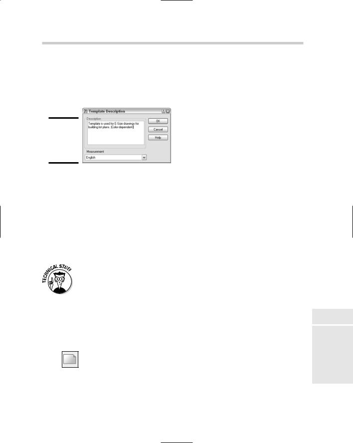
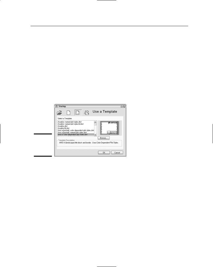
Book VIII, Chapter 1 is a primer of what is involved in establishing CAD standards. Drawing template files are one of the cornerstones of CAD standards because they help to promote the use of a company’s standards. However, drawing templates alone won’t get the job done. Creating and maintaining CAD standards is something of an art form when you consider everything you need to understand and appreciate to get drawings to look the way you want them to.

510 CAD Standards Overview

CAD standards affect both creating and editing geometry. This is because you are trying to make sure all your drawings look a certain way when they are plotted to paper. If everyone doesn’t follow CAD standards, you may edit someone else’s drawings only to discover that the established standards weren’t followed. Then, you have to spend additional time correcting the problem. Without CAD standards, all your objects would probably look the same, with none of the necessary variations.

The variations in a drawing help to convey a design idea that you have drafted. The variations might be in the form of different lineweights, linetypes, or even text styles. CAD standards cover the range of the drafting process from creation to presentation; for this reason, a specialized individual usually takes responsibility for CAD standards. In most midto large-size companies, CAD standards are determined by a CAD manager; in smaller companies, a senior level drafter often takes the responsibility. No matter who defines the CAD standards, they must be defined and understood by all drafters.

Below is an overview of some of the important things you should keep in mind when establishing or modifying a set of CAD standards:

Remember plotting. One of the key things to keep in mind when establishing CAD standards is how your drawings will look when they are plotted. This can affect such things as linetype scale, text size, dimension scale, and how you establish the use of lineweights for your objects.

Don’t make constant changes. We don’t recommend making changes to your CAD standards on a daily or even weekly basis; otherwise, you’re defeating the purpose of standards. And, as obvious as it sounds, remember to keep track of the changes you make. Changes might cause

problems for third-party applications or even possibly your own internal customization. Tracking changes provides a good way to keep track of when changes were made and also offers a way to communicate the standards to other drafters in the office when problems arise. Having an implementation date as to when the standards were updated ensures that everyone stays on the same page.

Keep it simple. One thing that can save you time is to create customization that incorporates your established CAD standards. If dimensions should be on a specific layer, consider customizing the menu items and toolbars so that they set a specific layer current before starting one of the dimension commands. You don’t have to be a power user to set up this type of customization, and it can cut down on errors and time.

Make it straightforward. CAD standards should not be in the form of complex manuals that require the use of a secret decoder ring to understand them. CAD standards should not only make sense to your internal drafters, but also to those with whom you share files. If you use cryptic

Using AutoCAD’s CAD Standards Tools 511

or abbreviated names for layers and styles, a new person may have a hard time stepping in and becoming efficient right away. The length of file names and the amount of memory were limited in the old (DOS) days, but now you can be more descriptive with the names you use for named objects.

The following lists the most common items you should consider incorporating into your CAD standards:

Blocks: (Book VI, Chapter 1)

Dimension styles: (Book III, Chapter 2)

Drawing Template (.DWT) Files: (Book VIII, Chapter 1)

Layers: (Book I, Chapter 5)

Layouts: (Book VII, Chapter 1)

Linetypes: (Book I, Chapter 5)

Page setups: (Book VII, Chapter 1)

Sheet Set Template (.DST) Files: (Book VII, Chapter 2)

Table styles: (Book III, Chapter 1)

Text styles: (Book III, Chapter 1)

Tool Palettes: (Book VI, Chapter 4)

Viewports: (Book VII, Chapter 1)

Views: (Book II, Chapter 3)

The remainder of this chapter focuses on the CAD standards tools found in AutoCAD, not AutoCAD LT.

Using AutoCAD’s CAD Standards Tools

AutoCAD provides several different tools that help keep drawings in sync with defined CAD standards. These tools are

Standards Manager: Used to configure and check for CAD standard violations.

Layer Translator: Used to configure layer mappings and change layers in a drawing to match those defined by your CAD standards.

Batch Standards Checker: Used to check a set of drawings against a defined set of CAD standards.

Book VIII

Chapter 2

Standards CAD