Добавил:
Опубликованный материал нарушает ваши авторские права? Сообщите нам.
Вуз: Предмет: Файл:

AutoCAD & AutoCAD LT All-In-One Desk Reference For Dummies (2006)

.pdf
Скачиваний:
90
Добавлен:
17.08.2013
Размер:
17.7 Mб
Скачать

492 Outputting Made Easy

1.Click one of the paper space layout tabs at the bottom of the drawing window.

2.Use one of the previously listed methods to open the Plot dialog box.

3.In the Plot dialog box, if necessary, specify the printer/plotter, paper size, and the number of copies.

4.Under the Plot Area heading, select what you want to plot in the drawing — often, you select Layout when plotting a paper space layout tab.

The drop-down list contains a number of options that you can select. The only difference between plotting the Model tab and a paper space layout tab in this case is that there is a Layout (Paper Space Layout Only) option in place of the Limits option. With the Layout option, all the objects on the layout that fall within the specific printable area of the specified paper size are printed.

5.In the Plot Offset area, specify an X and a Y offset from the edge of the printable area.

6.In the Plot Scale area, you specify a scale of 1:1 from the drop-down list in almost all cases.

A scale of 1:1 is selected because the scale of the model geometry is handled by each of the floating viewports on the layout.

7.Click Preview and verify that everything you want to plot will fit. After you have finished verifying your drawing, right-click and select Exit to return to the Plot dialog box.

8.Click OK.

Scaling your drawing

When you output your drawings, you must specify a specific scale for your drawing. This means you don’t use the Fit to Paper check box in the Plot dialog box much. If you are plotting from the Model tab, you specify a drawing scale. The drawing scale is usually always determined up-front before you begin drawing, and Chapter 5 of Book I explains how to calculate this value. If you are plotting from a paper space layout, you use a scale of 1 to 1 (1:1) because the scaling of the geometry is handled by the floating viewports on the layout.

More plotting options

The Plot dialog box has a button with an arrow on it located in the lowerright corner; by default, this button points to the right. This is a toggle that expands the Plot dialog box and reveals additional settings that are not required to output a drawing but do affect the appearance of the output. Below is a list of these additional options that are revealed when the More Options button is clicked:

Outputting Made Easy 493

Plot Style Table (Pen Assignments): The drop-down list allows you to specify a plot style that can be used to control the color and lineweights of the drawing during output. You can use the Edit button to the right of the drop-down list to edit the selected plot style.

Shaded Viewport Options: The options in this area are used to control how shaded and rendered views are output. The Shade Plot drop-down list allows you to specify how views that don’t have a specific visual style assigned to them are displayed. The Quality drop-down list and the DPI text box control the resolution at which shaded and rendered views are output.

Plot Options: The options in this area control a wide range of settings. Each one of the settings in this area is described in the following list:

Plot in Background: Determines whether control of AutoCAD is released after a plot is sent and the actual process of the plot is done in the background so you can get back to work sooner. If the option is unchecked, you have to wait until the plot has completed processing and is sent to the device. Enabling background plotting is slower; so if you need a plot right away, don’t use background plotting.

You can control background plotting through the Plot and Publish tab of the Options dialog box under the Background Processing Options area. There is an option for Plotting and one for Publishing (by default, Publishing is the only one checked). We discuss the Publishing option later in this chapter.

Plot Object Lineweights: Controls whether object lightweights assigned to layers and objects are used instead of the assigned plot style.

Plot with Plot Styles: Controls whether plot styles are used when plotting.

Plot Paperspace Last: Controls whether paper space geometry is plotted before model space geometry is.

Hide Paperspace Objects: Controls whether AutoCAD automatically performs the HIDE command on the paper space layout.

Plot Stamp On: Adds a plot stamp along the edge of the drawing when it is outputted. The plot stamp is configured using the PLOTSTAMP command.

Save Changes to Layout: Specifies whether changes to the plotting settings for the layout are saved when OK is clicked. This saves the changes for you so you don’t have to remember to click the Apply to Layout button before clicking OK.

Drawing Orientation: Controls whether the drawing is plotted in the portrait or landscape direction. You can also specify whether the drawing is plotted upside down by checking the Plot Upside-Down option.

Book VII

Chapter 3

Print,Publish

Plot,

494 Publishing Drawings

Publishing Drawings

Using the PLOT command to output your drawings is easy if you only have a few drawings that need to be outputted, but it can be a very large task if you have many drawings and layouts. Prior to AutoCAD 2004, you had to use an external batch plotting utility in order to output many drawings at one time. AutoCAD 2004 introduced a command called PUBLISH. The PUBLISH command allows you to batch a number of drawings together in order to output them all based on their defined page setups or override that page setup with one of your choice. The other feature that the PUBLISH command introduced was multisheet .DWF files. Prior to AutoCAD 2004, .DWF files were only capable of containing a single representation of a layout from either the Model tab or a paper space layout tab.

The PUBLISH command in AutoCAD LT only supports plotting to .DWF files.

To start the PUBLISH command, use one of the following methods:

File menu: Click File Publish.

Standard toolbar: Click the Publish button on the Standard toolbar.

Keyboard input: Type PUBLISH and press Enter.

Right-click over a layout tab after multiple layout tabs: From the shortcut menu, select Publish.

The following procedure takes you step-by-step through the basics of using the Publish dialog box:

1.Use one of the previously listed methods to open the Publish dialog box.

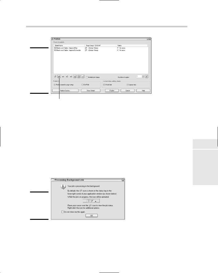
The Publish dialog box (see Figure 3-8) is displayed. If no layout tabs were selected, all the open drawings and their layouts are pulled into the dialog box.

2.In the Publish dialog box, click the Add Sheets button to add layouts from other drawings not currently open in AutoCAD.

The Select Drawings dialog box is displayed.

3.In the Select Drawings dialog box, browse to and select the drawings whose layouts you want to add to the Publish dialog box. Click Open.

The Select Drawings dialog box closes and all the layouts in the selected drawings are imported into the list box.

4.If you do not want a layout that has been imported, select the layout from the list and right-click. From the shortcut menu, select Remove, and the layout is removed.

Publishing Drawings 495

Figure 3-8:

The Publish dialog box makes printing multiple layouts and drawings a breeze.

Add Sheets button

5.Click Publish to start the publishing process.

6.The Save Sheet List dialog box is displayed. Click Yes to save the list of sheets out to a Drawing Set Description (.DSD) file. This file can then later be reopened in the Publish dialog box to republish all the layouts in the sheet list again.

If background plotting is enabled for publishing, the Processing Background Plot dialog box is displayed.

7.The Processing Background Plot dialog box (see Figure 3-9) is displayed when background plotting is enabled for the PLOT or PUBLISH command. By default, AutoCAD displays the same notification balloon as the PLOT command, when the PUBLISH command finishes.

Figure 3-9:

The background plotting message.

Book VII

Chapter 3

Print,Publish

Plot,

496 Book VII: Publishing Drawings

Book VIII

Collaboration

Contents at a Glance


Chapter 1: CAD Management: The Necessary Evil

..........................................................499

Chapter 2: CAD Standards..................................................................................................

509

Chapter 3: Working with Drawing Files ............................................................................

527

Chapter 4: Sharing Electronic Files ..................................................................................

547

Chapter 1: CAD Management:

The Necessary Evil

In This Chapter

Basics of CAD management

Managing the drafting environment

Creating a good foundation with drawing templates

AutoCAD & AutoCAD LT All-in-One Desk Reference For Dummies is designed to help both AutoCAD and AutoCAD LT users improve the

quality of the designs that they publish and effectively share them with others. As you progress through this book, you discover how to manage the drafting environment and CAD standards that are defined by your company, and some of the different ways to effectively work with drawing files.

CAD standards are one of those topics that is not discussed enough in the office, and yet they play a very important role in sharing drawing files. CAD standards ensure that the drawing files you create look similar to the drawing files that everyone else in the office creates. All the drawing files should have the same look and feel when they are presented to a potential client. If your work doesn’t have a uniform look, the client might get the impression that your company doesn’t have enough experience to handle the project.

After the drawing files have been completed, it’s usually time for them to be shared with others. During this stage of the project, you might find that printing hard copies and mailing them to the client or off-site team members takes too much time. If you need a timely response to a question or a change, you will most likely share files electronically. The type of file sharing you use depends on your target audience and the phase of the project. You might use a Web site to display files and images or use an Internet project site like Buzzsaw. In the end, you have to ensure that you are efficiently collaborating with your team and client.

Getting a Handle on the Basics of CAD Management

CAD management refers to managing the day-to-day operations involved in drafting with AutoCAD. CAD management is not necessarily the sole responsibility of one individual, but one individual often heads up the duties

500 Getting a Handle on the Basics of CAD Management

included in this area. If you are a midto large-size company, you might have a full-time CAD manager in this role; in a smaller company, the chores may be handled by a senior level drafter. The CAD manager may or may not be a supervisor at the company.

CAD management commonly covers the following areas:

Budgeting: Estimating the amount of money needed for a specific period of time for CAD-related expenses. This might be software upgrade costs, hardware purchases, office supplies (such as paper for the plotter), training costs, and even consulting fees.

CAD standards enforcement: Making sure that all drafters are following the company’s defined CAD standards — this is one of the responsibilities that many don’t like about CAD management. Ensuring that CAD standards are followed helps ensure that a high level of quality is maintained for drawings that are sent out.

Managing the drafting environment: Maintaining and managing support files through a centralized location to make sure that all drafters are using the same set of files when working with drawing files. This helps to reduce potential errors and the extra cost of keeping the files in sync if they are all running locally on each user’s own computer.

Conducting and coordinating training: Rolling out new procedures or even providing upgrade training for a new release. Training for upgrades might be outsourced, but the coordination of this training is usually handled by the individual responsible for CAD management in your office. Training might also be related to company rules and policies, and even departmental ones, if they exist.

Resource management: Overseeing the resource pool of CAD drafters to ensure that current and future projects are completed in a timely manner.

A project involves much more than just one drafter creating drawing files with AutoCAD; instead, a whole team with specialized skills is usually at work on a project. This team might include individuals who are responsible for overseeing the project, drafters, estimators, manufacturing and builders, and the client. This is the same approach that should be taken with CAD management and standards. One individual might have leadership responsibility, but everyone should be involved to a degree. Having everyone involved at some level helps to ensure that the standards are widely accepted and are uniform across an organization.

Due to the growing complexity of projects these days, more people from different areas of the company are getting involved, so having representation from across the company in defining CAD standards is a good idea. CAD standards shouldn’t just stay in the drafting department: The output from

Getting a Handle on the Basics of CAD Management 501

the drawing files might be used for marketing material, in print or on the Internet, and will surely end up in front of your clients as well. Clients end up reviewing drawings during many phases of a project, and, from these drawings, they build a perception of what kind of skill level your company has. For these reasons, many people need to get involved with CAD standards.

Some of the most interesting ideas for improving CAD standards and using the information maintained in a drawing file can come from different groups in a company coming together. That doesn’t mean that everyone in the company should have a direct vote in what is part of the CAD standards, but getting feedback from individuals in the company who deal with the information that is generated from a drawing file is a good idea. Often CAD standards are thought of in terms of drawings only, but they really encompass everything related to how the CAD information is used.

Here are some items that are part of the non-typical CAD standards that should be looked at as a company:

Title blocks: Information added to a title block could be used downstream to populate a project management system, if one exists.

Content of a drawing: How the drawing is created can affect how its information can be used downstream for things such as renderings and animations that might be done by an internal or external art department.

Annotation, such as notes and dimensions: Some notes on a drawing might be there for legal reasons; it is good to have a company view on these types of notes because the information might already be covered in a bid packet or specification document.

AutoCAD support file locations: Companies want to make sure that file access is optimal for all users throughout the company. This ensures an efficient working environment and also ensures that everything is properly backed up in case of a catastrophe.

File exchanging practices (use of e-mail or FTP sites): Policies in place

for the use of e-mail might delay the sending of information for a project. An example of an e-mail policy that can affect the sending or receiving of files for a project can be the total allowable size of all files coming in or going out during normal business hours. It’s wise to communicate with internal and external departments to see what can be sent out efficiently without conflicting with company e-mail policy.

Drawing name convention and storage locations: Naming conventions are important so that individuals in the company can find a drawing file in a timely manner. This could affect how the files might be archived and the file rights that individuals may need to access them. Storing these types of files in a centralized location on a network drive accessible to everyone is good practice.

Book VIII

Chapter 1

Management: CADNecessary The

Evil