472 Managing Drawings with a Sheet Set
9.If you select Choose Blocks in the Drawing File, select a block from the list box.
10.Click OK.
The Select Block dialog box closes, and you are returned to the List of Blocks dialog box. The selected file and/or block(s) are added to the list box.
11.In the List of Blocks dialog box, click OK.
The List of Blocks dialog box closes, and you are returned to the Sheet Set Properties dialog box where the callout blocks are added to the Callout Blocks property.
12.In the Sheet Set Properties dialog box, click OK.
The Sheet Set Properties dialog box closes, and the changes are saved.
Adding resource drawings
Sheet sets allow you to take advantage of model space views that you have defined in drawings. The location of these drawings needs to be made available to the Sheet Set Manager in order for you to place them onto a sheet.
Resource drawings are defined through the Model Views tab of the Sheet Set Manager. The locations that are added for resource drawings most commonly contain details or elevations but could also be for plans.
The following steps show how to define a drawing resource location for a sheet set, and assume that you already have a sheet set open in the Sheet Set Manager. To open a sheet set, refer to the section, “Opening a sheet set.”
1.In the Sheet Set Manager on the Model Views tab, double-click the Add New Location node under the Locations section.
The Browse for Folder dialog box appears.
2.In the Browse for Folder dialog box, specify the folder that contains the drawings with the model views that you want to place on a sheet. Click Open.
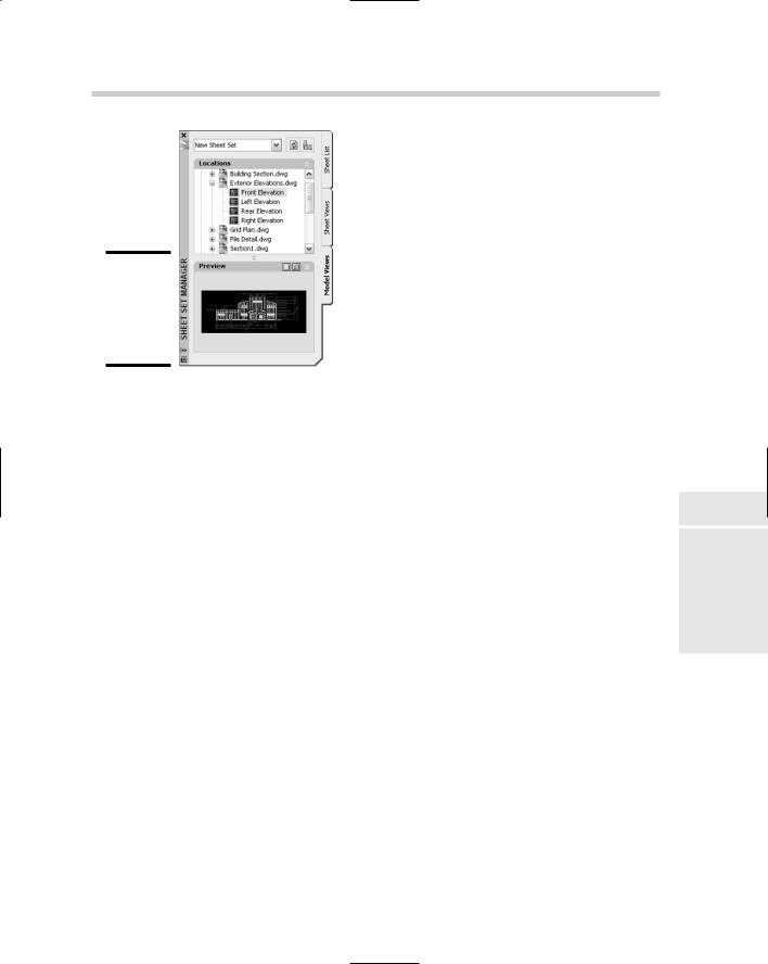
Clicking Open after selecting the folder that contains the drawing files with the model views in them closes the Browse for Folder dialog box and returns you to the Sheet Set Manager. AutoCAD loads all the drawings into the Locations section on the Sheet Set Manager that are contained in the specified folder (see Figure 2-17).
Managing Drawings with a Sheet Set 473
Figure 2-17:
Resource drawings available to the sheet set.
Adding model views to a sheet
After you have set up the callout and label blocks and the resource drawings for the sheet set, you are ready to place model space views on a sheet. Model space views must first be created and saved in a drawing that is in the location where your resource drawings are stored. A model view can be assigned a category and a layer state. The layer state affects how layers appear in the viewport that is created when the model view is added to a sheet. The category is used to organize views on the Sheet Views tab of the Sheet Set Manager. For information on model views, see Book II.
Model views that are placed on a sheet don’t introduce any new concepts in AutoCAD, but they do use a combination of existing features. Model views use named views to define what is displayed, xrefs to get the geometry in the drawing, viewports to display the xref’d drawing, and blocks and attributes to help link the information from a sheet set into the drawing.
The following procedure explains how to place a model view on a sheet and adjust the views number and title. The procedure assumes you have already defined a resource location for drawings, specified a label block to use, set up the properties for creating a new sheet, and have a sheet set open. If you need help with any of these tasks, refer to previous sections in this chapter for some help.
1.On the Sheet tab of the Sheet Set Manager, create a new sheet for the model views that you want to add to the sheet set, or open an existing sheet. Make sure that the sheet is open before you continue.
Book VII
Chapter 2
Sets SheetRegret
without
474 Managing Drawings with a Sheet Set
2.On the Model Views tab, click the plus-sign next to one of the drawings defined by the resource location under the Location section.
The node for the drawing is expanded and any views are displayed below it.
3.Select one of the views below the drawing with the left mouse button and continue to hold down the mouse button and drag the view over the drawing window.
As you drag the view, the name of the view is dragged with the cursor.
4.Release the mouse over the drawing window to start the referencing process.
A preview of the view is displayed for dragging on the screen along with the label block below the view.
5.Right-click over the drawing window to specify a specific scale for the view.
AutoCAD guesses at a scale based on the size of the drawing and the view that is being referenced. By right-clicking, you can choose a scale from a shortcut menu.
6.Select a scale from the shortcut menu for the view.
The preview image that is being dragged is updated to reflect the new scale.
7.Pick a point in the drawing window to place the model view, and create the viewport and insert the label block.
The viewport is created based on the specified scale, and the label block is inserted below the viewport.
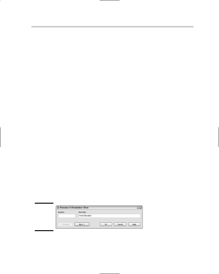
8.On the Sheet Views tab, locate the view that was just added in the tree based on the sheet name or category of the view. Right-click over the view and select Rename & Renumber.
The Rename & Renumber View dialog box appears (see Figure 2-18).
Figure 2-18:
Renaming and renumbering a view.
476 Publishing, eTransmitting, and Archiving a Sheet Set
Publishing, eTransmitting, and Archiving a Sheet Set
After you create all the sheets for your sheet set and add any views that you need on a sheet, you can package the set and get it off to the client. An entire sheet set or selected sheets can be published using the page setup that is assigned to each layout or a page setup override, along with the ability to publish the sheets to a multi-sheet DWF file. To work with the publish options for a sheet set, right-click the top-level node of the sheet set and choose an option from the Publish submenu. Publishing is explained in the next chapter of this book.
eTransmitting and archiving a sheet set are very similar. When you eTransmit a sheet set, you are packaging all the drawing and support files for that project to send to a client or customer electronically. When you archive a sheet set, you are essentially doing an eTransmit, but the package is not sent to a client or customer. You can eTransmit a subset within a sheet set, but you can’t archive a subset. Archiving can only be done for the whole sheet set.
You can start the eTransmit process from the shortcut menu after rightclicking the sheet set or a subset node and selecting eTransmit, or by using the ETRANSMIT command outside the Sheet Set Manager when the sheet set is open. Doing so opens the Create Transmittal dialog box.
To create an archive of the sheet set, right-click the sheet set node and click Archive, or use the ARCHIVE command when the sheet set is open in the Sheet Set Manager. Doing so opens the Archive a Sheet Set dialog box.
For information on using the eTransmit and archive features of sheet sets, refer to the online Help system that comes with AutoCAD.
Chapter 3: Print, Plot, Publish
In This Chapter
Configuring printers and plotters
Defining and using plot styles
Plotting from the Model tab and paper space
Publishing drawings
Even with the growth of the Internet and online project collaboration sites, many people still want or need drawings to be delivered in hard
copy format — in other words, printed. Many years ago, the idea of a paperless society was born with the introduction of the Internet. Despite what some predicted, however, our dependency on paper has not dwindled that much, so you still need to hang onto those printers and plotters for the time being.
Throughout this book, we’ve covered many of the necessary techniques to set up your drawings and prepare them for output. Page setups and layouts play an important role in getting your drawings onto a sheet of paper, but in order to get to the finish line, you need to do a little bit more work yet. This chapter looks at configuring a printer or plotter to output your drawings and also covers plot styles, which can be used to affect output.
You Say Printing, We Say Plotting,
They Say Publishing
Printing, plotting, and publishing are all terms that we cover in this chapter. For the most part, they all produce the same result: a hard copy or an electronic file. The process of getting to the end result varies based on which path you decide to take. In AutoCAD, printing usually involves small drawings that can be output to a laser or inkjet printer. Output is usually done on an 81⁄2x11 sheet of paper, but might also include 11x17, based on your printer’s capabilities. Most AutoCAD users think of printing as something that word processing and spreadsheet programs do, whereas plotting is what AutoCAD does.
Plotting is a common way of outputting a drawing from AutoCAD to a hard copy because drawing files are usually printed on very large sheets of paper. Plotting requires specialized hardware that holds rolls of paper in different
478 You Say Printing, We Say Plotting, They Say Publishing
widths for printing drawings that are greater in size than 81⁄2x11 or 11x17. Some older plotters required you to manually load sheets of paper. Based on the plotter you have available, it might also be able to print 81⁄2x11 and 11x17 sheets. When a drawing is printed or plotted, only the Model tab or a paper space layout can be sent to a device at a single time. To get around this limitation, you can use the publishing feature in AutoCAD.
Publishing is used to output more than just the Model tab or one paper space layout at a time. Publishing allows you to set up multiple drawings and layouts contained in the files for outputting to a device. This can make sending out a drawing set easier because a list of drawings and layouts can be saved for future use. You can publish all the sheets in a sheet set directly from the Sheet Set Manager. For more information on sheet sets and the Sheet Set Manager, see Chapter 2 of this book.
Working with drivers
To use printers and plotters with software, you must often install additional software called print drivers. Print drivers come from the hardware manufacturer and provide a way for software applications like AutoCAD to communicate with them. So when you or someone from your IT department installs a printer through Windows, you are setting up what AutoCAD calls a system printer. System printers are the printers that AutoCAD and other Windowsbased applications have access to. For most applications, this is enough, but AutoCAD is not just any ordinary program.
AutoCAD allows manufacturers to develop a form of print drivers that can enhance the abilities of their printers or plotters in a way that can’t be done through a standard print driver. AutoCAD refers to these drivers as non-system drivers, which means the driver can’t be installed as part of the Windows operating system. Most companies that develop plotters, such as HewlettPackard (HP), Xerox, and Océ, develop custom drivers that AutoCAD can use. These drivers are often much more efficient and flexible in communicating with the printer or plotter the driver is designed for. Some of the improvements in non-system drivers allow you to control which paper sizes are available to choose from, as well as additional features like line merge and AutoSpool.
Setting up and using system drivers is much easier than setting up and using non-system drivers. The ease of setup and use is balanced out by the better control over plotting that non-system drivers offer. Because printing and plotting in AutoCAD is so different from other Windows-based applications, the Help system offers some great information on the topic. For additional information on print drivers, launch the online Help for AutoCAD and select Driver and Peripheral Guide; then choose Use Plotters and Printers from the Contents tab.
You Say Printing, We Say Plotting, They Say Publishing 479
Configuring a printer or plotter
Configuring a device for AutoCAD usually requires a little more work than installing a system printer. At times, you might even find that configuring a system printer as a non-system printer might have some advantages. The first thing you want to do before configuring a new device is to determine whether it might have already been configured for you. (CAD managers and IT personnel often set up printers and plotters to ensure that there is consistency to the output.) After you have determined which devices you have available, you can set up a new one if you need to.
Determining which printers and plotters are available
The first step on the road to plotting is making sure that AutoCAD can access the device that you want to output to. The following procedure opens the Options dialog box and checks to see which system and non-system printers are available:
1.Choose Tools Options.
The Options dialog box is displayed.
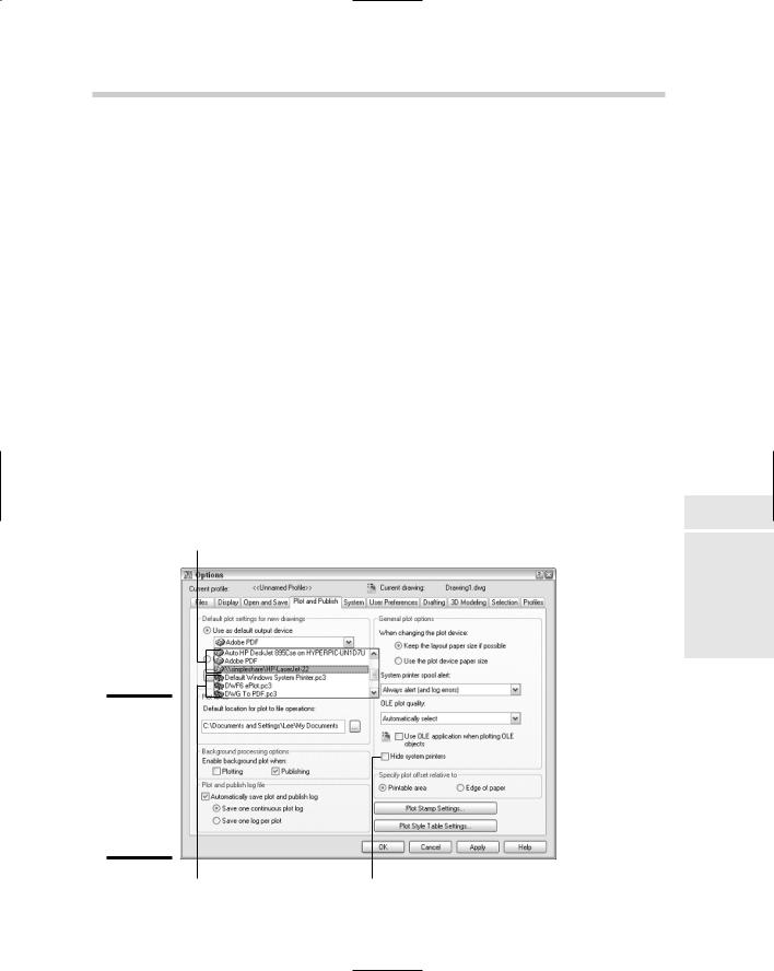
2.In the Options dialog box, click the Plot and Publish tab.
The Plot and Publish tab (see Figure 3-1) is set current.
Book VII
Chapter 3
System printers
Print,Publish
Plot,
Figure 3-1:
Many of the plotting and publish options in AutoCAD are in the Options dialog box.
Non-system printers |
Hide system printer option |
480 You Say Printing, We Say Plotting, They Say Publishing
3.Click the down arrow on the Use as Default Output Device drop-down list under the Default Plot Settings for New Drawings section.
Both system and non-system printers are displayed in the drop-down list, unless the Hide System Printers option has been checked under the General Plot Options section.
•System printers are indicated by an icon that shows a small laser printer with a sheet of paper on top next to its configured name in Windows.
•Non-system printers are indicated by an icon that shows a plotter with a sheet of paper coming out in front next to its configured name in AutoCAD.
The non-system printers that are configured for AutoCAD are displayed in the list with a file extension .PC3. The .PC3 file extension stands for AutoCAD Plotter Configuration and is the third generation of the file format. The .PC3 files were first used with AutoCAD 2000.
4.Click somewhere other than the Use as Default Output Device dropdown list to close the drop-down list.
AutoCAD has access to all the system printers and some select nonsystem printers out of the box. The non-system printers that are available are capable of producing output to an electronic file only, such as to a .DWF or .PDF file, and some types of image files. Now that you have an idea of which printers and plotters are available to you from AutoCAD, you should know if you are missing one that your office uses on a daily basis for production drawings.
5.Click Cancel.
The Options dialog box closes.
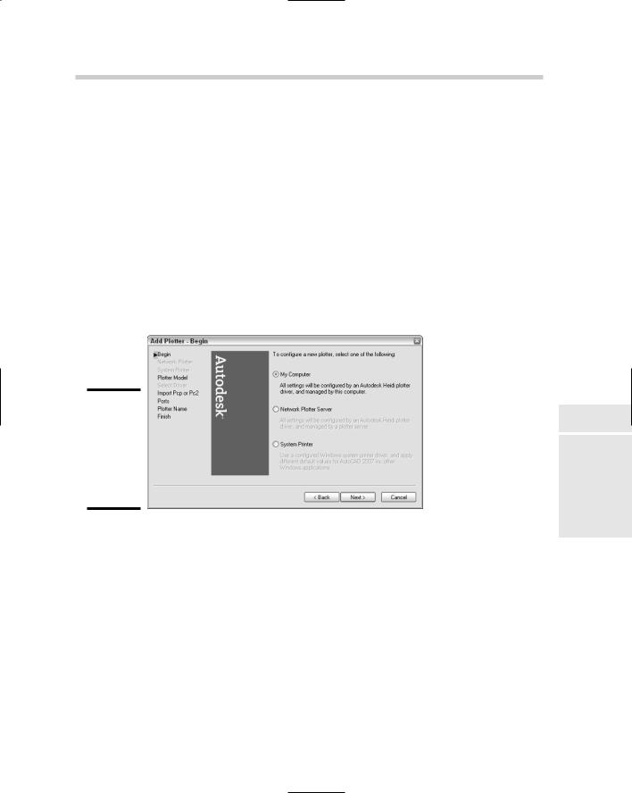
Setting up a non-system printer
AutoCAD provides a wizard to help you set up non-system printers. The wizard can be accessed from within AutoCAD or through the Windows Control Panel. No matter which method you use, the Add Plotter Wizard is displayed. You can use the PLOTTERMANAGER command to display a window that allows you to access the wizard and any previously defined non-system printers.
To start the Plotter Manager, follow one of these methods:
File menu: Select File Plotter Manager.
Keyboard input: Type PLOTTERMANAGER and press Enter.
Select Tools Options to display the Options dialog box: Make sure the Plot and Publish tab is selected. Click the Add or Configure Plotter button under the Default Plot Settings for New Drawings section.