

AutoCAD & AutoCAD LT All-In-One Desk Reference For Dummies (2006)
.pdf462 Managing Drawings with a Sheet Set
8.Select the layout you want to use as the sheet template in the Select a Layout to Create New Sheets list box. Click OK.
The Select Layout as Drawing Template dialog box closes, and the specified drawing file and selected layout are applied to the Sheet Creation Template property in the Sheet Set Properties dialog box.
9.In the Sheet Set Properties dialog box under the Sheet Creation area, specify Yes or No in the Prompt for Template property.
The Prompt for Template property controls whether the template specified in the Sheet creation template is used when a new sheet is created. You can choose to use that sheet creation template or one of your own choosing.
10.Click OK.
The Sheet Set Properties dialog box closes and the changes to the properties are applied to the sheet set.
Setting up drawing template settings for a subset
Setting up a subset for when a new sheet is created under the subset is similar to setting up a sheet set. Refer to the previous topic for information on setting up the properties that are related to when a new sheet is added to a sheet set. The following steps provide a quick walk-through of how to access the properties of a subset (not a full in-depth walk-through of each property) and assume that you have a sheet set open in the Sheet Set Manager. To open a sheet set, refer to the section, “Opening a sheet set.”
1.In the Sheet Set Manager on the Sheet List tab, right-click the subset that you want to adjust the properties for.
The subset shortcut menu appears.
2.On the shortcut menu, click Properties.
The Subset Properties dialog box appears.
3.In the Subset Properties dialog box, specify the new location where the sheets will be created, the drawing template that will be used for the new sheets added to the subset, and whether the user will be prompted to specify a drawing template when a new sheet is added to the subset.
The properties in the Subset Properties dialog box, except for the Subset name field, are the same as those under the Sheet Creation area of the Sheet Set Properties dialog box. See the topic “Setting up drawing template settings for a sheet set” for more information on these properties.
4.Click OK.
The Subset Properties dialog box closes and the changes to the properties are saved.
Managing Drawings with a Sheet Set 463
Adding a new sheet
A new sheet can be added to a sheet set or a subset. How the new sheet is defined is based on the properties that have been set up for the sheet set or the subset. When a new sheet is created, a new drawing file is created. The new drawing then has its layout referenced into the sheet set file at the location that the new sheet was created. Once the properties have been defined for the sheet set or subset, a new sheet is rather easy to create.
The following steps show how to add a new sheet to either the root of a sheet set or a subset, and assume that you already have a sheet set open in the Sheet Set Manager. To open a sheet set, refer to the section, “Opening a sheet set.”
1.In the Sheet Set Manager on the Sheet List tab, right-click the sheet set or subset to which you want to add a new sheet.
The shortcut menu appears.
2.On the shortcut menu, click New Sheet.
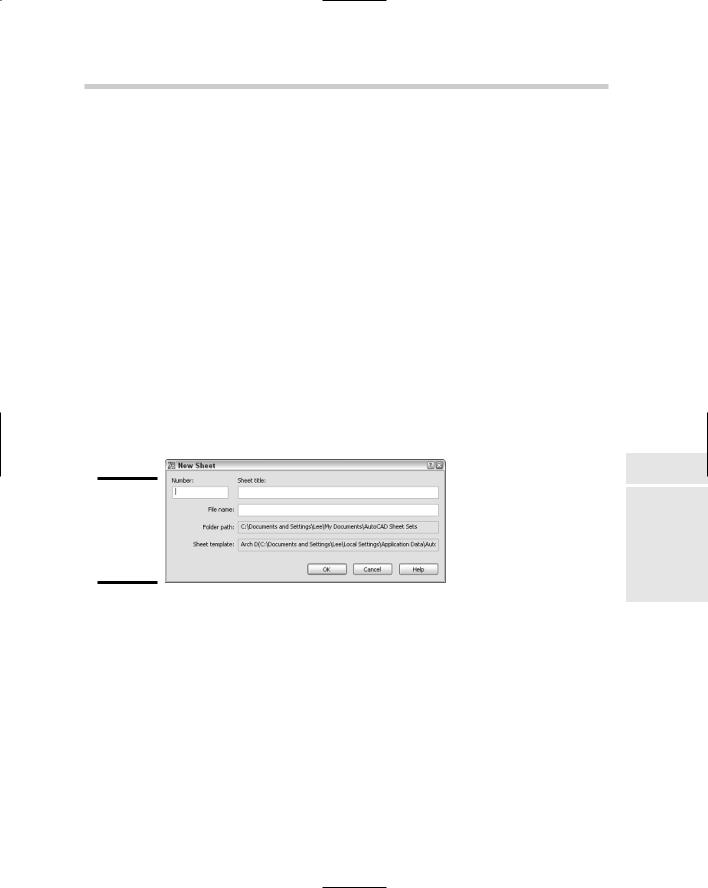
The New Sheet dialog box appears (see Figure 2-9). The dialog box allows you to specify a number, title, and filename for the new sheet.
Figure 2-9:
Adding a new sheet to a sheet set or subset.
3.In the New Sheet dialog box, enter a drawing number for the sheet in the Number text box.
The number can be displayed in a title block through the use of a field, can be displayed as part of the index sheet table, and is shown in the tree view on the Sheet List tab.
4.Enter a title for the sheet in the Sheet Title text box.
The title can be displayed in a title block through the use of a field or as part of the index sheet table, and is shown in the tree view on the Sheet List tab.
5.Enter a filename for the sheet in the File Name text box.
AutoCAD uses the filename you enter to save the new sheet to the specified location in the Folder Path text box.
Book VII
Chapter 2
Sets SheetRegret
without

464 Managing Drawings with a Sheet Set
6.Click OK.
The New Sheet dialog box closes and the new sheet is added to the sheet set or the subset.
You can control the order in which sheets and subsets appear on the Sheet List tab by dragging them up and down. Sheets can also be added to a subset by dragging them onto the subset or into a specific location within the subset.
The Sheet Set Manager in AutoCAD 2007 allows you to select and move multiple sheets at once, unlike previous releases that allowed you to move only a single sheet at a time.
Opening a sheet
Opening a sheet in a sheet set is straightforward. You can just double-click on the sheet, and the drawing opens with the referencing layout displayed. If you want, you can also right-click over a sheet and select Open or Open read-only from the shortcut menu.
Removing, renaming, and renumbering a sheet
At times you may find yourself needing to remove, rename, and renumber a sheet based on whether it is being moved in a sheet set or may no longer be needed. Removing a sheet from a sheet set allows you to get rid of it when it no longer is needed. To remove a sheet from a sheet set, right-click on the sheet and choose Remove sheet from the shortcut menu. When asked to confirm the removal of the sheet, click OK. AutoCAD removes the sheet from the sheet set only, and the actual drawing file is left alone.
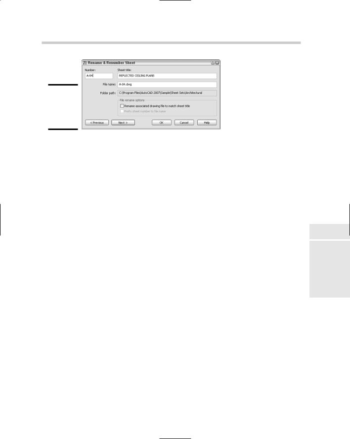
Changing the title and number of a sheet can be done through the Rename & Renumber Sheet dialog box (see Figure 2-10). The Rename & Renumber dialog box allows you to change the number of the sheet along with its title, and you can even change the actual filename. To rename and renumber a sheet, right-click over the sheet and select Rename & Renumber for the shortcut menu. Change the number and title in the dialog box. You can navigate to the next or previous sheet and change its title or number without leaving the dialog box.
Although you can use AutoCAD or Windows Explorer to rename drawing files, it is best to rename drawings that are linked to a sheet set file using the Sheet Set Manager to avoid missing files.
Managing Drawings with a Sheet Set 465
Figure 2-10:
Renaming and renumbering a sheet.
The ability to move to the previous sheet in the Rename & Renumber dialog box was first added to AutoCAD 2006. AutoCAD 2006 also introduced the ability to change the file name of the drawing for a sheet using the Rename & Renumber dialog box.
Sheet set and sheet properties
Sheet sets and individual sheets use two types of properties, standard and custom. Standard properties are available for you to use without doing any additional setup. Standard properties can be accessed by right-clicking over the top level node of the sheet set or a sheet and selecting Properties. Based on which one you right-click over, different properties are available to you. Some of these properties can be referenced in a text or attribute object via fields.
Custom properties require a little more work because you need to define the property before you can use it. Custom properties allow you to incorporate the use of sheet sets into your current drafting process much more easily by allowing you to define properties that you might be accustomed to using during your project management cycle for client, drafter, or project information. Even though sheet sets and sheets come with predefined properties for you to use, they do not cover everything that you might want to store with a sheet set or sheet. Custom properties, like standard properties, can be displayed in a title block via fields.
The following steps show how to define a custom property for a sheet and then change its value, and assume that you already have a sheet set open in the Sheet Set Manager. To open a sheet set, refer to the section, “Opening a sheet set.”
1.In the Sheet Set Manager on the Sheet List tab, right-click the top level node that displays the sheet set’s name.
The shortcut menu appears.
2.On the shortcut menu, click Properties.
The Sheet Set Properties dialog box appears.
Book VII
Chapter 2
Sets SheetRegret
without
466 Managing Drawings with a Sheet Set
3.In the Sheet Set Properties dialog box, click Edit Custom Properties.
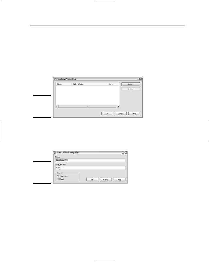
The Custom Properties dialog box appears (see Figure 2-11). The dialog box allows for adding and modifying custom properties that you can have at the sheet or sheet set level. These custom properties allow you to populate information down to title blocks in your sheets so that the information can be edited from a central location without opening each sheet individually.
Figure 2-11:
The Custom Properties dialog box.
4.In the Custom Properties dialog box, click Add.
The Add Custom Property dialog box appears (see Figure 2-12). The dialog box allows for defining a new sheet set or sheet property.
Figure 2-12:
Adding a custom property.
5.In the Add Custom Property dialog box, enter a name for the custom property in the Name text box.
The name of the field can be pretty much anything you want to use. The value entered appears in the Sheet Set Properties, Sheet Properties, and Field dialog boxes.
6.Enter an initial value for the property in the Default Value text box.
This value is the default value for the property.
Managing Drawings with a Sheet Set 467
7.Select either Sheet Set or Sheet from the Owner area based on the type of property you want to create. This procedure uses the Sheet as the Owner type.
The owner type controls where the property will be accessible from, even though both types of custom properties are created through the Sheet Set Properties dialog box.
8.Click OK.
The Add Custom Property dialog box closes and you are returned to the Custom Properties dialog box. The new custom property should now be listed. Once the custom property has been created, you can only change its default value. If you want to change its name or owner, you will need to delete the custom property and then re-create it. Be careful about deleting custom properties; if the custom property is used in a field, it will become unresolved because it no longer exists. Double-click the default value for the custom property to edit the value.
9.In the Custom Properties dialog box, click OK.
The Custom Properties dialog box closes, and you are returned to the Sheet Set Properties dialog box. If you added a custom property that had
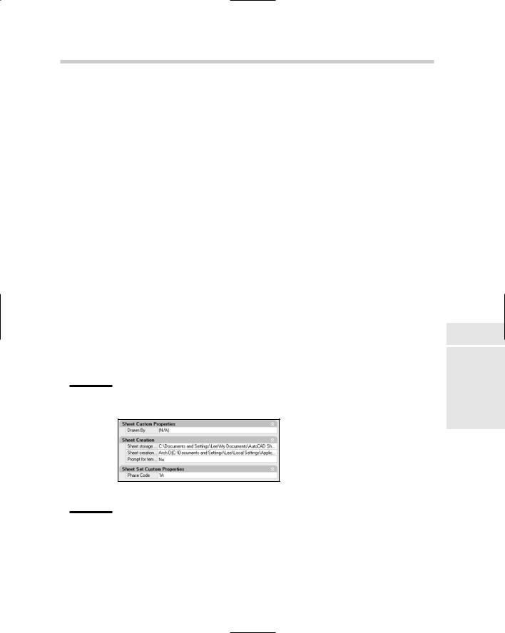
its owner set to Sheet Set, the properties would be displayed under the Sheet Set Custom Properties section (see Figure 2-13) of the Sheet Set Properties dialog box. Also notice that custom properties that are designated as an owner of Sheet are displayed under the Sheet Custom Properties section. This allows you to change the default value of a sheet custom property.
Figure 2-13:
Both sheet and sheet set custom properties are displayed
in the Sheet Set Properties dialog box.
10.In the Sheet Set Properties dialog box, click OK.
The Sheet Set Properties dialog box closes and you are returned to the Sheet Set Manager.
Book VII
Chapter 2
Sets SheetRegret
without
468 Managing Drawings with a Sheet Set
11.In the Sheet Set Manager, right-click over the sheet you want to change the custom properties for.
The shortcut menu is displayed.
12.On the shortcut menu, click Properties.
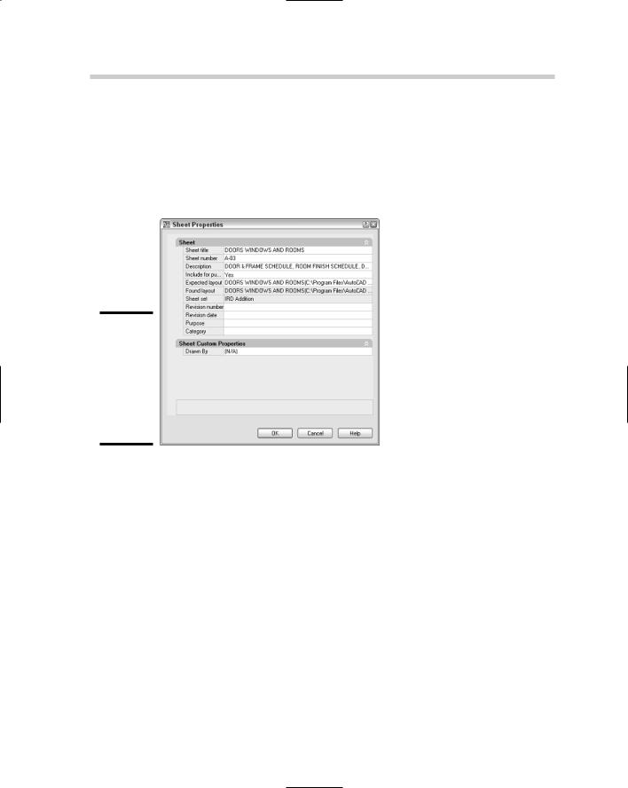
The Sheet Properties dialog box appears (see Figure 2-14).
Figure 2-14:
Sheet properties are changed through the Sheet Properties dialog box.
13.In the Sheet Properties dialog box, change the custom sheet property under the Sheet Custom Properties section.
Click in the text box next to the custom property and make the change to its value.
14.Click OK.
The Custom Properties dialog box closes and you are returned to the Sheet Set Manager. Both sheet set and sheet properties and their values are displayed in the Details area at the bottom of the Sheet Set Manager when a node in the tree view of the Sheet List tab is selected. If the Details area is not displayed, click the Details button just below the tree view on the Sheet List tab.
Setting up callouts and label blocks
Callout and label blocks are used with model space views that are dragged and dropped from the Model Views tab onto a sheet. Label blocks are

Managing Drawings with a Sheet Set 469
automatically placed under the model space view when you drop them onto a sheet. They commonly hold the view number, view title, and the viewport’s scale. A view is assigned a number and a title by accessing the properties of a view that has been placed on a sheet from the Sheet Views tab. Placing views on a sheet are discussed further in the section, “Adding model views to a sheet.”
Callout blocks, unlike label blocks, are not automatically placed in a drawing. A callout block typically has the view number and the sheet in which the view is placed. The callout may point to a particular side of a building plan, indicating on the sheet where the elevation is located.
When a callout block is added to a sheet, AutoCAD creates a hyperlink back to the sheet the view is placed on. This allows you to move to the sheet with the view on it rather quickly by pressing and holding down the Ctrl key while double-clicking on the callout block.
Callout and label blocks use fields to reference information that is contained in the sheet set. These fields are defined through the use of the SheetSetPlaceholder field name under the category SheetSet in the Fields dialog box. To learn more about fields, refer to Book III. For information on creating blocks, refer to Book VI.
Setting up label blocks
The following steps show how to define label blocks for placing with model space views, and assume that you have a sheet set open in the Sheet Set Manager. To open a sheet set, refer to the section, “Opening a sheet set.”
1.In the Sheet Set Manager on the Sheet List tab, right-click the top level node that displays the sheet set’s name.
The shortcut menu appears.
2.Click Properties.
The Sheet Set Properties dialog box appears.
3.In the Sheet Set area of the Sheet Set Properties dialog box, click the Label Block for Views text box to display an ellipsis button.
The ellipsis button appears.
4.Click the ellipsis button for the Label Block for Views property to specify a block or drawing file.
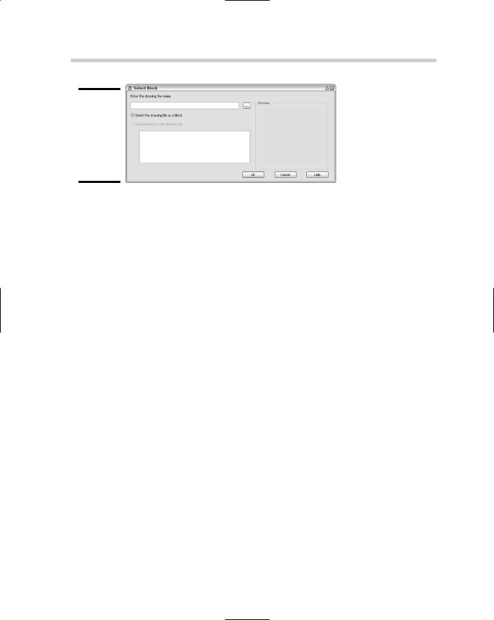
The Select Block dialog box appears (see Figure 2-15). You can use this dialog box to browse for a drawing file and then use the drawing file as the label block, or select a block from the drawing as a label block.
Book VII
Chapter 2
Sets SheetRegret
without
470 Managing Drawings with a Sheet Set
Figure 2-15:
Select Block dialog box allows you to select
a block contained in a drawing.
5.In the Select Block dialog box, click the ellipsis button to the right of the Enter the Drawing Name text box.
The Select Drawing dialog box appears, allowing you to select a drawing or drawing template (DWT) file that contains the block you want to use as a label block or is the label block saved as a file.
6.In the Select Drawing dialog box, browse to and select the drawing or drawing template file that contains the label block you want to use when placing model space views. Click Open.
The Select Drawing dialog box closes and the selected file is added to the Select Block dialog box.
7.In the Select Block dialog box, select either the Select the Drawing as a Block or Choose Blocks in the Drawing File option.
The selected option determines which block is used for a label block.
8.If you select Choose Blocks in the Drawing File, select a block from the list box.
The selected block is used as the label block.
9.Click OK.
The Select Block dialog box closes, and the block name and path are assigned to the Label Block for Views property in the Sheet Set Properties dialog box.
10.In the Sheet Set Properties dialog box, click OK.
The Sheet Set Properties dialog box closes, and the changes are saved.
Setting up callout blocks
Setting up callout blocks is very similar to setting up a label block, with the exception of being able to associate multiple blocks from a drawing for use
Managing Drawings with a Sheet Set 471
as callout blocks. The following steps show how to define which callout blocks are available for placing in a drawing to reference a model space view on a sheet, and assume that you have a sheet set open in the Sheet Set Manager. To open a sheet set, refer to the section, “Opening a sheet set.”
1.In the Sheet List tab of the Sheet Set Manager, right-click the top level node that displays the sheet set’s name.
2.On the shortcut menu, click Properties.
3.In the Sheet Set Properties dialog box under the Sheet Set area, click the Callout Blocks text box to display an ellipsis button.
4.Click the ellipsis button for the Callout Blocks property to specify a block or drawing file.
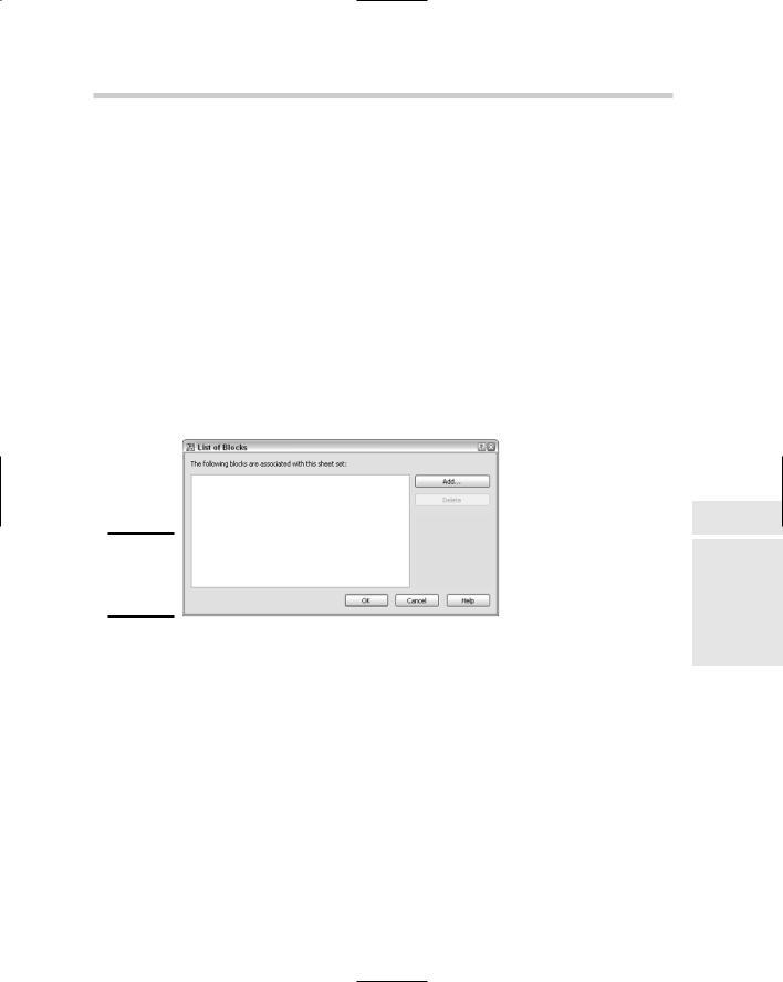
The List of Blocks dialog box appears, allowing you to browse for drawing files, and use a drawing file as the callout block or select a block from the drawing as a callout block (see Figure 2-16).
Figure 2-16:
The List
of Blocks dialog box.
5.In the List of Blocks dialog box, click Add.
The Select Block dialog box appears, allowing you to browse for a drawing file, and use the drawing file as the callout block or select a block(s) from the drawing as a callout block.
6.In the Select Block dialog box, click the ellipsis button to the right of the Enter the Drawing Name text box.
7.In the Select Drawing dialog box, select the drawing or drawing template file that contains the label block you want to use when placing model space views. Click Open.
8.In the Select Block dialog box, select either the Select the Drawing as a Block or Choose Blocks in the Drawing File option.
Book VII
Chapter 2
Sets SheetRegret
without