442 Looking at a Model through Viewports
AutoCAD offers two types of viewports, tiled and floating. Tiled viewports are created only on the Model tab and provide a way to work in the drawing without outputting it. Floating viewports are created only on a paper space layout and are used to organize a drawing for output. The following sections cover how to create and work with floating viewports on a layout.
Defining a viewport’s shape
AutoCAD supports two types of floating viewports, rectangular and irregular (polygonal and closed objects, such as a circle or spline). Rectangular viewports are the most common of the two, but being able to create a viewport from a circle or polyline object can allow you to conserve space on a layout or jazz one up for plotting. The VPORTS command is used to create both rectangular and irregular viewports.
AutoCAD LT does not support the creation of irregular floating viewports.
To start the VPORTS command, use one of the following methods:
View menu. Choose View Viewports, and a submenu with nine options is displayed.
Viewports toolbar. Click the Display Viewports Dialog button on the Viewports toolbar. You can also choose to use the buttons Single Viewport, Polygonal Viewport, or Convert Object to Viewport on the toolbar.
Layouts toolbar. Click the Display Viewports Dialog button on the Layouts toolbar.
Keyboard input. Type VPORTS and press Enter.
Creating a rectangular viewport
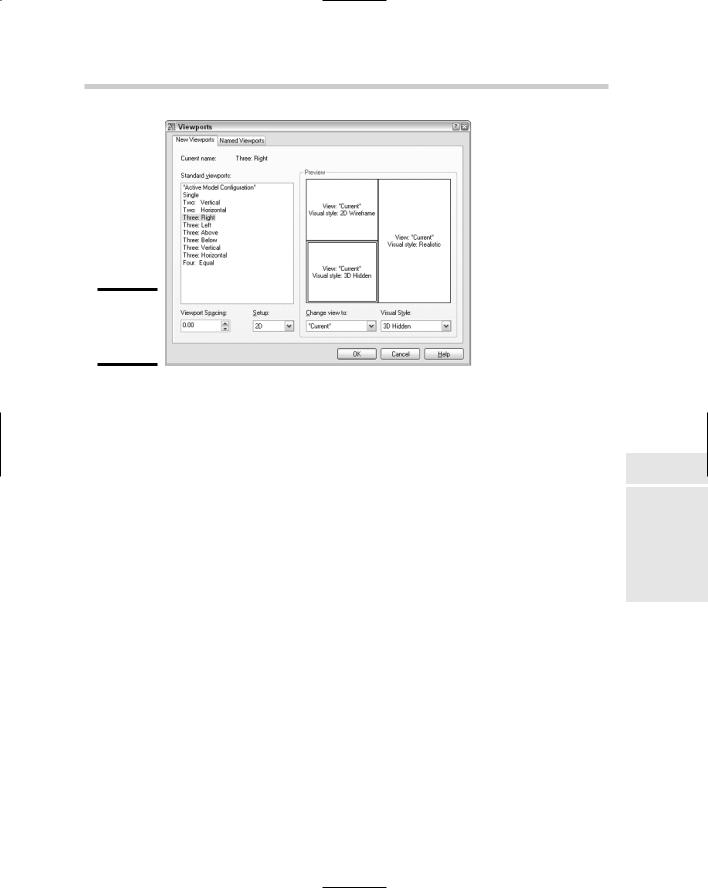
Rectangular viewports are the most common and the easiest to create. The Viewports dialog box, shown in Figure 1-9, offers some standard configurations for quickly laying out rectangular viewports. You can specify up to four viewports with a different visual style and view for each one. The Viewports dialog box offers some default views for 3D drawings, such as Top, Left, and Southwest.
Looking at a Model through Viewports 443
Figure 1-9:
The Viewports dialog box.
To add a viewport configuration to a layout, follow these steps:
1.Select the paper space layout that you want to create floating viewports on. Make sure that no viewports already exist on the layout by erasing any that are, or be sure to have enough area to add some additional ones.
2.Initiate the VPORTS command by using one of the previously described methods.
The Viewports dialog box is displayed. This dialog box allows you to create some basic viewport layout configurations.
3. In the Viewports dialog box, make sure that you are on the New
Viewports tab. Select the configuration you want to use from the Standard Viewports list box.
The Preview area updates to reflect the viewport configuration you selected.
4.In the Viewport Spacing text box, enter the amount of space you want between the viewports that are created. This only affects the viewports that you are currently creating.
The size of the spacing should be a rather small number since you need to specify a scale of 1 in the Plot dialog box when plotting a paper space layout.
Book VII
Chapter 1
Setup Page
444 Looking at a Model through Viewports
5.If your drawing is 3D in nature, select 3D from the Setup drop-down list or leave it as the default 2D value.
If you specify 3D, you have some additional views to choose from under the Change View To drop-down list. Otherwise, there is no other difference between specifying 2D and 3D.
6.In the Preview area, click the different sections of the preview that represent the viewports that will be created later.
When you select in the different viewports of the Preview section, you are setting that viewport current for adjusting its view and visual style.
7.With the viewport set current, select a named view from the Change View To drop-down list.
The selected named view is displayed in the Preview section for the current viewport.
8.With the viewport set current, select a visual style from the Visual Style drop-down list.
The selected visual style is displayed in the Preview section for the current viewport.
9.Repeat Steps 5 through 7 for each of the viewports in the Preview section.
10.Click OK.
The Viewports dialog box closes, and you are returned to the drawing window where the prompt below is displayed at the command line or in a dynamic tooltip.
Specify first corner or [Fit] <Fit>:
11.In the drawing window, specify the first point on the layout in the printable area where you want to create the viewports.
You are specifying a rectangular area where the viewports will be created. The next prompt below is then displayed at the command line or in a dynamic tooltip.
Specify opposite corner:
12. In the drawing window, specify the opposite corner to finish defining the area where you want the viewports to be created.
The viewports are created in the defined area based on the options specified in the Viewports dialog box. You should notice that the objects on the Model tab are displayed in each of the viewports.
Creating an irregular viewport
Irregular viewports are created by using the command line version of the VPORTS command. The command line version of the command is accessible
446 Looking at a Model through Viewports
Controlling scale
Paper space layouts are plotted at a scale of 1:1, so in order to get the objects in the viewports to be plotted and displayed correctly, you have to specify a scale for each viewport. You do this by using the scale list on the Viewports toolbar or using the Properties palette. The following procedure uses the Properties palette to change the scale for a floating viewport.
1.Select a viewport on a paper space layout for which you want to change the scale.
The grips for the selected viewport appear.
2.With the viewport selected, right-click and select Properties from the shortcut menu to display the Properties palette.
The Properties palette appears.
3. In the Properties palette, select the scale for the viewport from the
Standard Scale drop-down list.
The viewport is updated to display the objects on the Model tab at the specified scale. You can also specify a custom scale by typing the scale value in the Custom Scale text box on the Properties palette.
You can use the SCALELISTEDIT command to display the Edit Scale List dialog box to control which scales are available for use in the program. This controls the list of scales in places like the Viewports toolbar and the Plot dialog box.
Controlling the display within a viewport
You can move in and out of viewports on a paper space layout by doubleclicking inside the viewport. This places you in model space so you can interact with the objects on the Model tab. By entering the viewport this way, you can control which part of the objects on the Model tab are displayed through the viewport by panning. Once you have the objects positioned correctly, you can then lock the viewport. To lock the display of a viewport, select the viewport, and then right-click, select Display Locked, and then click Yes or No.
At times you may find that you may want to edit objects through a viewport. In this case, there is a way to open a viewport so that it fills the entire drawing area. If you double-click on a viewport object or its border, the viewport is
448 Looking at a Model through Viewports
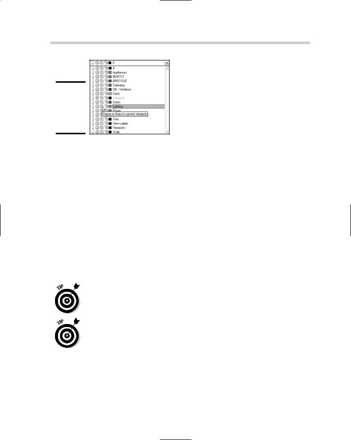
Figure 1-11:
Freezing a layer in the current viewport only.
Another way to control the display of objects in a viewport is by completely turning off the viewport altogether. The viewport remains in the drawing, but any objects that would normally be displayed through the viewport do not. To control the display of the objects through a viewport, select the viewport, and right-click. From the shortcut menu select Display Viewport Objects, and then click Yes or No.
Modifying a Viewport
Viewports can be modified by using the Properties palette, MOVE and COPY commands, grips, and many other methods. Grip editing to adjust the size, shape, and location of a viewport is by far one of the most efficient ways of modifying viewports. Adjusting a viewport by using grips has no effect on the scale or the viewpoint within the viewport. It will, however, affect which objects are displayed through the viewport. Grips are not the only way that you can control the shape of a viewport after it has been created. The VPCLIP command also allows you to control the shape of the viewport by re-creating its overall shape, and not affect the viewpoint or scale of the viewport.
You can use the VPCLIP command to create irregularly shaped viewports by selecting the viewport and then the closed object you want to use as the new clipping boundary.
You can use the COPYCLIP command to copy viewports between layouts. When you go to paste the copied objects viewports to a different layout, AutoCAD turns off the display of the objects within the viewport. To turn the display of the objects back on, select a viewport and right-click. From the shortcut menu, choose Display Viewport Objects, and then click Yes or No.
Chapter 2: Sheet Sets without Regret
In This Chapter
Understanding a sheet set
Creating a sheet set
Managing drawings with a sheet set
Publishing, eTransmitting, and archiving a Sheet Set
Sheet sets were first introduced in AutoCAD 2005 and are still a relatively new concept in AutoCAD. They are based on an old drafting concept
called a drawing set. Sheet sets are designed to be the digital equivalent of a drawing set that contains numerous drawings, which often include refer-
ences to details, sections, and elevations within the drawing set along with a drawing or two that contain an index of all drawings in the set.
AutoCAD LT does not support Sheet Sets.
Overview of a Sheet Set
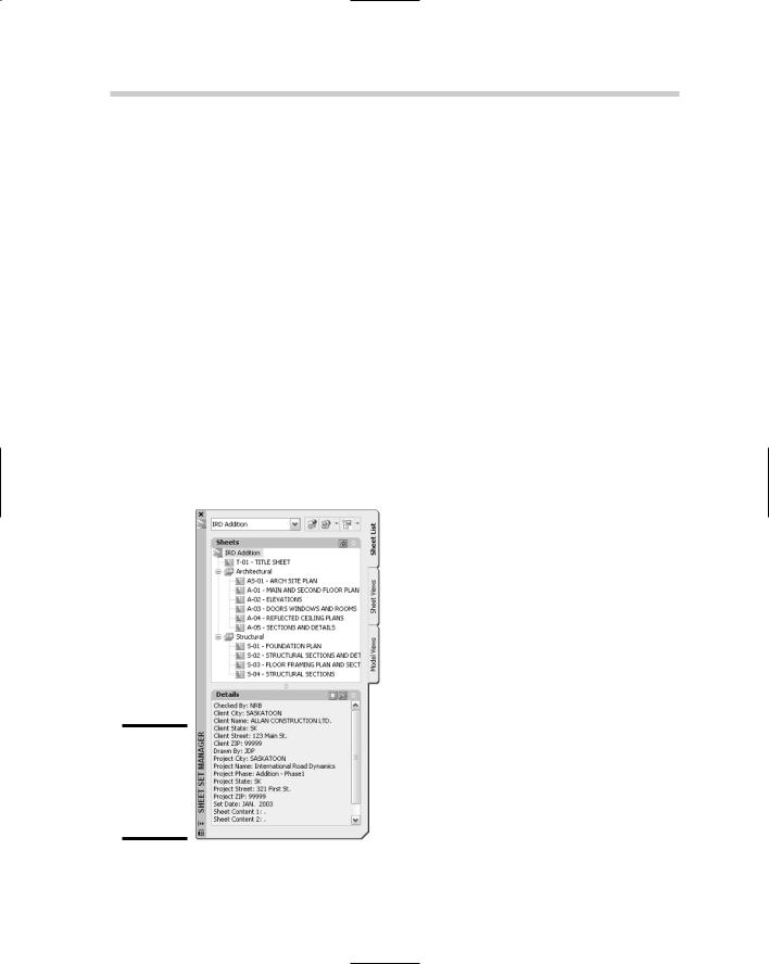
Sheet sets are designed to take advantage of the existing drawings that you have been creating over the years. A sheet set contains sheets, which are references to paper space layouts — sorry, the Model tab cannot be used as a sheet. If you are using the Model tab for plotting and publishing today, you will need to switch to the use of paper space layouts in order to take advantage of sheet sets. A sheet set and all of the references to its sheets are stored in a file with the extension of DST and are accessed through the Sheet Set Manager (see Figure 2-1). By using references to the drawing files, it is possible to use your own directory structures while being able to take advantage of the benefits that sheet sets offer. Some of the benefits that sheet sets offer are
Fast file access. Because a sheet set knows right where a file is located, drawings can be accessed in a very short amount of time without the need to browse and open a file.
Consistent drawing creation. Sheet sets can be set up to specify the directory structure and location in which new sheets should be created when they are added to the sheet set. Along with simplifying the specification and the location of a drawing file when a sheet is created, you
450 Overview of a Sheet Set
can specify which drawing template (DWT) file should be used to create the sheet.
Quickly make updates. Sheet sets allow you to create references to views on sheets (paper space layouts) and manage the names and numbers of views. This allows you to quickly renumber a view and not have to worry about exactly where that view is placed. The next time the drawing is opened, the numbering is updated. This also works very well for project information in a title block that is on a paper space layout.
Publishing drawings. Creating a drawing set can be time-consuming when it is time to package things up and to get them ready to send off to the client. Sheet sets allow you to organize drawings and then be able to publish the entire set or the selected drawings quickly.
Packaging up drawings. During the project cycle revisions will happen, there is no doubt about that. Sheet sets allow for eTransmitting or archiving of an entire set of drawings.
Create an index table of sheets. One of the things that can take time to generate, but is fairly automated with sheet sets, is the creation of an index of all the sheets in the set. Since all the sheets are named and numbered in the sheet set, it is possible to create an index in a few clicks.
Figure 2-1:
Sheet Set
Manager allows you to work with DST files.