

AutoCAD & AutoCAD LT All-In-One Desk Reference For Dummies (2006)
.pdf432 Preparing for Output with Page Setups
Plot style table. Specifies which plot style should be used during the outputting of a drawing. A plot style can control the color and
lineweights of objects as they are sent to a printer, plotter, or electronic file.
Shaded viewport options. Controls how viewports defined on a layout should be plotted.
Plot options. Options in this area control how the final plot appears. This area also controls whether plot styles and lineweights are used during output.
Drawing orientation. Controls the direction in which the drawing should be output — portrait or landscape. You can also specify that the output be generated upside-down. Based on the type of device you are using for output, you may need to specify the upside-down option in order for the output to come out correctly.
Working with page setups
Page setups can be added to a drawing in a couple of different ways. You can use the Page Setup Manager and define a new page setup through the Page Setup dialog box, or you can import them from an existing drawing or drawing template (DWT) file. When you create a page setup or import it into a drawing, you can then assign it to a layout. If the page setup is later changed, all the layouts that were assigned the page setup are updated.
To start the PAGESETUP command and to access the Page Setup Manager, use one of the following methods:
File menu. Choose File Page Setup Manager.
Layouts toolbar. Click the Page Setup Manager button on the Layouts toolbar.
Keyboard input. Type PAGESETUP and press Enter.
Layout tab shortcut menu. When the Model and layout tabs are visible, right-click the current layout tab at the bottom of the drawing window and select Page Setup Manager.
Creating a page setup
When you create a page setup, you first need to determine if you are plotting from the Model tab or a layout. If you create a page setup for the Model tab, it can be used only with the Model tab. Any page setups created with a paper space layout active are available only for paper space layouts.
Preparing for Output with Page Setups 433
To create a page setup, follow these steps:
1.Use any of the previously mentioned methods to initiate the PAGESETUP command.
2.Choose File Page Setup Manager.
The Page Setup Manager is displayed.
3.In the Page Setup Manager, click New.
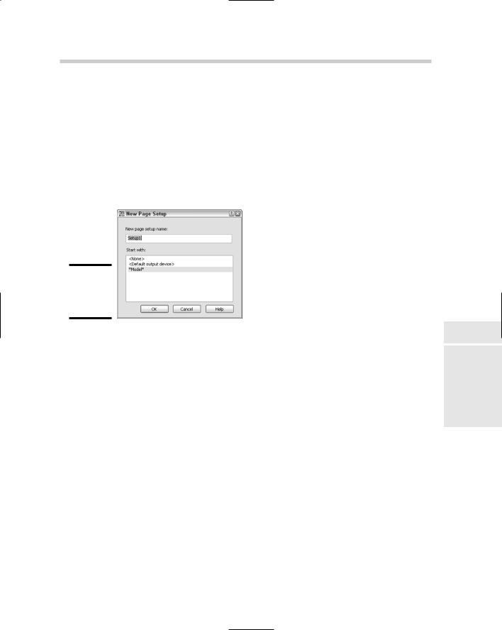
The New Page Setup dialog box appears (see Figure 1-3).
Figure 1-3:
Naming the new page setup.
4.In the New Page Setup dialog box, enter the name of page setup in the New Page Setup Name text box.
The name entered is displayed in the text box.
5.Select one of the existing page setups from the Start With list box or choose <None> to start with default settings only.
Selecting a page setup from the Start With list box can be helpful if a page setup already exists that is close to the one you want to create.
6.Click OK.
The New Page Setup dialog box closes and the Page Setup dialog box appears.
7.In the Page Setup dialog box, specify the different options you want to be associated with the page setup.
The options that you select will be used with the layout that the page setup is associated with when it is plotted or published.
8.Click OK.
The Page Setup dialog box closes and you are returned to the Page Setup Manager. The page setup that was created should now be listed in the list box under the Page Setups section.
Book VII
Chapter 1
Setup Page
434 Preparing for Output with Page Setups
9.In the Page Setup Manager, click Close.
The Page Setup Manager closes and you are returned to the drawing window.
At the bottom of the Page Setup Manager is a check box labeled Display when creating a new layout. If the check box is selected, the Page Setup Manager appears when a layout is initialized the first time or when a new layout is created. The option is also available from the Display tab of the Options dialog box but is called Show Page Setup Manager for new layouts.
Importing a page setup
Importing a page setup is the fastest and most efficient way of adding a page setup to a drawing. To import a page setup from an existing drawing file, follow these steps:
1.Use any of the previously mentioned methods to initiate the PAGESETUP command.
The Page Setup Manager appears.
2.In the Page Setup Manager, click Import.
The Select Page Setup From File dialog box appears.
3.In the Select Page Setup From File dialog box, browse and select a drawing, drawing template (DWT), or DXF file that contains the page setup that you want to import. Click Open.
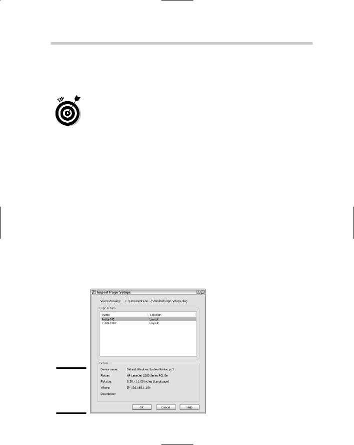
The Import Page Setups dialog box appears with the available page setups listed (see Figure 1-4).
Figure 1-4:
Reusing page setups through importing.

Organizing a Drawing with Layouts 435
4.In the Import Page Setups dialog box, select the page setup you want to import from the Page Setups list box. You can select multiple page setups by holding Ctrl+Shift when you select page setups. Click OK.
The Import Page Setups dialog box closes and you are returned to the Page Setup Manager. The selected page setups are displayed in the Page Setups list box.
5.In the Page Setup Manager, click Close.
The Page Setup Manager closes and you are returned to the drawing window.
Assigning a page setup to a layout
After you create or import a page setup into your drawing, you can put it to work. To set a page setup to the current layout, follow these steps:
1.Use any of the previously mentioned methods to initiate the PAGESETUP command.
2.Right-click over the active tab, and choose Page Setup Manager from the shortcut menu.
The Page Setup Manager is displayed. The current layout’s name is displayed along the top and to the right of the label Current layout.
3.In the Page Setup Manger, select the page setup from the Page Setups list box.
Layouts are listed first in the list box and have an asterisk (*) before and after their names. Named page setups are listed after the layouts in the list box. If a layout has been assigned a named page setup, the name of the page setup is displayed after the layout’s name and placed within a set of parentheses.
4.Click Set Current.
The page setup is assigned to the current layout and its name is displayed to the right of the Current page setup label under the Page Setups section.
5.Click Close.
The Page Setup Manager closes and you are returned to the drawing window.
Organizing a Drawing with Layouts
Layouts are used to help control how a drawing is plotted or published. In AutoCAD R14 and earlier, layouts were referred to as Model Space and Paper Space. This changed with the introduction of layouts with AutoCAD 2000. AutoCAD R14 and earlier supported a single Model Space and a single Paper
Book VII
Chapter 1
Setup Page
436 Organizing a Drawing with Layouts
Space. AutoCAD 2000 made it possible to have one Model tab which represents the old Model Space and multiple paper space layouts.
AutoCAD 2007 and AutoCAD LT 2007 allow you to save all the way back
to the AutoCAD R14 file format, which doesn’t support multiple paper space layouts. In order to exchange a drawing that contains multiple layouts with a user on AutoCAD R14, you will need to set each layout as current, one at a time, and save the drawing out once for each layout.
Think of a layout as a piece of paper and a way to visually organize how parts of your drawing will appear on the sheet of paper. Generally, you should do all your designing and drawing on the Model tab, but there are some exceptions to this rule. At times, you may need to add annotation and dimensions that are related to part of your drawing that is being displayed through a floating viewport.
Floating viewports are small windows into the Model tab of the drawing and are covered later in this chapter in the section “Looking at a Model through Viewports.” Most commonly, you will find a title block that has been inserted or referenced on a layout, in addition to one or more floating viewports.
Working with layouts
Layouts, unlike page setups, are not managed through a dialog box. Layouts are managed through the tabs that appear along the bottom of the drawing window. Everything that you might need for creating or modifying a layout is at the tip of your cursor. The LAYOUT command is used for working with paper space layouts.
To start the LAYOUT command, use one of the following methods:
Insert menu. Choose Insert Layout, and a submenu with three different options are displayed.
Layouts toolbar. Click the New Layout or Layout from Template button on the Layouts toolbar.
Keyboard input. Type LAYOUT and press Enter.
Layout tab shortcut menu. When the Model and layout tabs are visible, right-click a layout tab at the bottom of the drawing window and select one of the different options above the top separator bar of the menu.
Creating a layout using the Create Layout Wizard
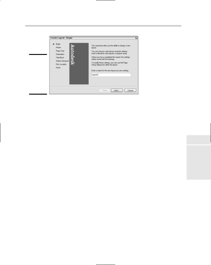
Layouts contain title blocks, viewports, and references to page setups. To make the process of creating a layout as efficient as possible, AutoCAD comes with a wizard called Create Layout and is launched by the LAYOUTWIZARD command (see Figure 1-5). The Create Layout Wizard steps you through the process of creating and setting up a layout.
Organizing a Drawing with Layouts 437
Figure 1-5:
The Create Layout Wizard gets you on the fast track to creating a layout.
To use the Create Layout Wizard, follow these steps:
1.Launch the Create Layout Wizard by using one of the previously described methods.
The Create Layout Wizard appears.
2.In the Create Layout Wizard on the Begin page, enter a name in the Enter a Name for the New Layout You Are Creating text box. Click Next.
The name of the layout can be a maximum of 255 characters, which is a very long layout name. The layout tab is roughly 31 characters (at the most).
3.On the Printer page, select one of the printers that are available, including both system printers and PC3 files. Click Next.
The printer you specify is used as the default output device for the layout.
4.On the Paper Size page, select one of the available paper sizes from the drop-down list and the drawing units. Click Next.
The paper size is assigned to the layout and used during output. The available paper sizes that you can select from are determined by the printer that you previously selected. Drawing units are typically in inches or millimeters, but if you choose a printer that generates an image file, you also have the option of pixels. The paper size is displayed under the Paper Size in Units section.
5.On the Orientation page, select either Portrait or Landscape. Click Next.
The orientation controls which way the paper is turned for output.
Book VII
Chapter 1
Setup Page

438 Organizing a Drawing with Layouts
6.On the Title Block page, select one of the available drawings to use for the title block on the layout and specify how the title block is placed on the layout, either as a Block or an Xref. Click Next.
The title blocks that you are able to choose from are the ones that come with AutoCAD by default. The title blocks are located in the path that is specified under the Template Settings and Drawing Template File Location found on the Files tab of the Options dialog box.
7.On the Define Viewports page, select one of the four available viewport setups. The page also allows you to control the scale of the viewports, spacing between each viewport and the number of viewports created. Click Next.
The available options are usually not exactly what you want, but they do allow for a good starting point. Remember, you can resize and adjust the scale of the viewports using grips and the Properties palette later.
8.On the Pick Location page, click the Select Location button to specify the area of the layout you want the viewports to be created in. Click Next.
As mentioned in the previous step, you can modify the viewports once they are on the layout using grips and the Properties palette.
9.On the Finish page, click Finish.
The Create Layout Wizard closes, and the new layout is created based on the options that you specified during the wizard.
Importing a layout
The Create Layout Wizard is nice, but there are some things you will most likely need to do after you use the wizard, such as assigning a page setup to adjust other settings of the layout to control the output that is not part of the wizard. As with page setups, AutoCAD allows you to import layouts that are in an existing drawing. Importing a layout allows you to spend less time setting up your drawing and more time on drafting.
To import a layout into a drawing, follow these steps:
1.Choose Insert Layout Layout from Template.
The Select Template From File dialog box is displayed. This dialog box allows you to browse for a drawing, drawing template (DWT), or DXF file that contains the layout you want to import.
2.In the Select Template From File dialog box, select the drawing, drawing template (DWT), or DXF file that contains the layout you want to import. Click Open.
Organizing a Drawing with Layouts 439
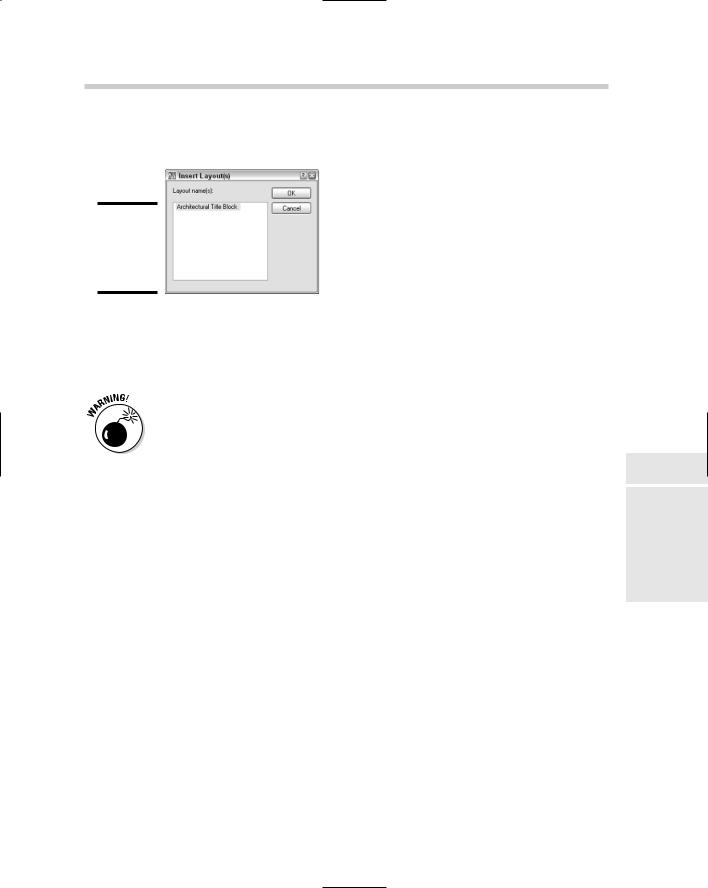
The Insert Layout(s) dialog box appears and lists the available paper space layouts that can be imported (see Figure 1-6).
Figure 1-6:
Importing an existing layout from a drawing.
3.In the Insert Layout(s) dialog box, select a layout or multiple layouts from the list box. Click OK.
The layouts are imported to the drawing and are positioned to the right of the last layout tab.
Page setups are not automatically imported when importing a layout. If you want to keep the page setup with the layout, you must first import the page setup and then the layout separately.
Modifying a layout
Layout tabs can be modified in a variety of ways. They can be removed from a drawing or repositioned. You can use the LAYOUT command for many of these tasks, but using the shortcut menu of a layout tab is the most flexible. If you right-click a layout tab, you can access the following options for modifying a layout:
Delete. Allows you to remove the selected layout or layouts from the drawing.
Rename. Displays the Rename Layout dialog box so that you can change the text string that appears on the layout tab.
Move or Copy. Displays the Move and Copy dialog box so you can control the order in which layouts are displayed and allows you to quickly create a copy of an existing layout in the drawing.
Select All Layouts. Allows you to select all the tabs in the drawing except for the Model tab.
Book VII
Chapter 1
Setup Page
440 Organizing a Drawing with Layouts
Navigating Layouts
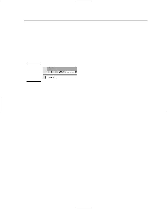
A drawing contains at least one layout at all times and one Model tab but may contain many more layouts than that. Once you get past about four or five layouts, navigating layouts becomes a little more difficult as tabs start becoming hidden from view. AutoCAD offers a couple of different ways to navigate through the tabs that represent the layouts in the drawing file. The most common way to navigate the layout tabs is to use the set of four controls located at the bottom of the drawing window (see Figure 1-7).
Figure 1-7:
Layout navigation controls.
The far left control jumps to the very first layout tab, and the far right control jumps to the very last layout tab. The two controls located in the middle allow you to step one layout tab at a time backward and forward. You can also use the keyboard combinations Ctrl+Page Up and Ctrl+Page Down to step backward and forward one layout tab at a time.
In this version of AutoCAD, you can turn off the display of the layout tabs and still be able to access different layouts efficiently. If you are using an earlier release, you can turn off the display of the layout tabs, but navigating layouts is difficult. If you right-click a layout tab, you have the option to Hide Layout and Model tabs from the shortcut menu. When the layout tabs are hidden, three new controls are displayed in the status bar area to allow you to access the Model tab and the different paper space layouts in the drawing.
Appearance of layouts
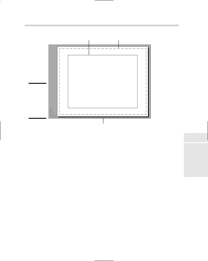
The appearance of layouts and the layout tab can be controlled through the Display tab of the Options dialog box. To access the Options dialog box, select the Tools menu and then Options. The Layout Element section controls many of the visual cues that are present when a layout tab is current (see Figure 1-8). These include the printable area, the overall paper size, and a shadow to give the paper an appearance of depth.
Looking at a Model through Viewports 441
Viewport Printable area
Figure 1-8:
Layouts visually display printable area and paper size.
Paper edge
The background color can be modified so that it is easier to tell that you are in a layout versus the Model tab, or you can make them appear the same. The different color options are available through the Colors button under the Window Elements section of the Display tab in the Options dialog box. It is also possible to control the color of the UCS Icon when a layout tab is active through the UCS Icon dialog box. The UCS Icon dialog box can be displayed by selecting the View menu, Display, UCS Icon, and then Properties.
Looking at a Model through Viewports
Layouts by themselves do not provide all the necessary requirements for getting your drawing set up and ready for output. When you use the Create Layout Wizard, you are prompted to define viewports and provide a scale for them, so you know viewports are important on a layout. Viewports allow you to see part or all of the objects that are on the Model tab and to have these objects displayed at a specific scale.
Book VII
Chapter 1
Setup Page