422 AutoCAD Calculator
Using QuickCalc with the Properties palette
The following procedure uses the QuickCalc dialog box through the
Properties palette to reduce the radius of a circle by a factor of .75.
1.Choose Tools Palettes Properties.
The Properties palette appears.
2.In the drawing window, select the circle for which you want to reduce the radius by a factor of .75.
3.On the Properties palette, select the Radius property.
The Calculator icon should be displayed at the far right of the text box for the radius.
4.Click the Calculator icon.
The QuickCalc dialog box is displayed.
5.In the QuickCalc dialog box, click behind the radius value that was added from the Properties palette in the Input Box. Type the expression *.75 after the radius value and press Enter.
The result of the radius multiplied by .75 is displayed in the Input Box, and the full expression and result are added to the History Area.
6.Click Apply.
The result of the expression is assigned to the Radius property of the circle in the Properties palette and the circle is updated in the drawing window.
If the system variable CALCINPUT is set to 1, you can enter expressions directly into many of the text boxes that appear in dialog boxes and on palettes in AutoCAD. For example, if you enter =1+2.75 in the Thickness property of the Properties palette and press Alt+Enter, the expression is evaluated to the value of 3.75. If you are using AutoCAD and not AutoCAD LT, you can use AutoLISP variables in your expressions.
Using QuickCalc with a command
The following procedure uses the QuickCalc dialog box at the Specify radius of circle or [Diameter] command prompt of the Circle command.
1.Choose Draw Circle Center, Radius.
The CIRCLE command starts and displays the following command prompt at the command line:
Specify center point for circle or [3P/2P/Ttr (tan tan radius)]:
424 Auditing and Recovering Drawings
or the dynamic input tooltip. Specify Yes or No to automatically fix any errors that AutoCAD detects in the drawing file. Any errors that are fixed are displayed in the Text Window; press F2 to display the Text Window and review the corrections that AutoCAD made. Below is an example of the output in the Text Window.
Auditing Header |
|
|
|
Auditing Tables |
|
|
|
Auditing Entities |
Pass |
1 |
Pass 1 600 |
objects |
audited |
Auditing Entities |
Pass |
2 |
AcDbDimStyleTableRecord: “14-ROMANS-115”
Not in Table
Added |
|
Pass 2 600 |
objects audited |
Auditing Blocks
9 Blocks audited Total errors found 1 fixed 1
Recovering a drawing
If AutoCAD can’t successfully open a drawing in AutoCAD due to a problem with the file, it will suggest performing a recovery on the drawing file. The RECOVER command is used to select a drawing file that needs to be recovered; during this process AutoCAD audits a drawing file in memory for any defects and attempts to fix them. In most cases the recovery of a drawing file is successful, but there are times when all errors can’t be fixed.
To recover a drawing, you use the RECOVER command (choose File Drawing Utilities Recover). The Select File dialog box appears. This dialog box allows you to select the drawing you want to recover. AutoCAD audits the drawing, and if everything is successful, a message box appears informing you that the recovery and audit of the drawing file completed successfully. Any errors that are fixed are displayed in the text window. Press F2 to display the Text Window and review the corrections that AutoCAD made.
Auditing and Recovering Drawings 425
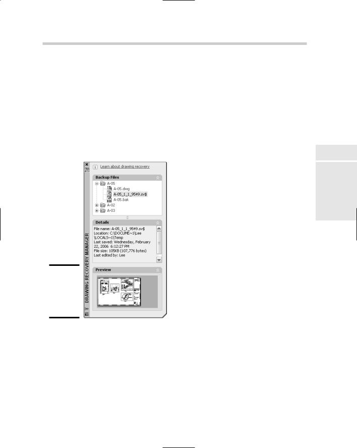
Using the Drawing Recovery Manager
If AutoCAD happens to crash, you will usually get the option to save any open files before AutoCAD completely closes. When you open AutoCAD the next time, the Drawing Recovery Manager palette appears (see Figure 5-4). The Drawing Recovery Manager palette was introduced in AutoCAD
2006 and it shows the files that are available for you to recover after a crash. The files that AutoCAD usually displays in the Drawing Recovery Manager palette are the drawing files that you saved on the way out of AutoCAD during the crash, the last saved version of the drawing files, the last autosave file associated with the drawing files, and the last back-up file of the drawing files that were open.
Book VI
Chapter 5
Utilities AutoCAD
Figure 5-4:
The Drawing Recovery Manager palette.
Each drawing that was open during the crash is represented by a blue folder. Expand the folder by clicking the plus sign next to the drawing that contains the files that can be recovered. Once the folder is expanded, you can select a file to see its details and view a preview, or double-click the file to open it in
426 Auditing and Recovering Drawings
a drawing window. After the file is opened, save it with the same name as the original drawing file that was open when AutoCAD crashed (to replace the corrupted file) or save the file with a different name (to create a new copy). If one of the backup or autosave files overwrites the original file that was open during the crash, all the files that are related to that drawing are removed from the Drawing Recovery Manager palette.
Chapter 1: Page Setup
In This Chapter
Preparing for output with page setups
Organizing a drawing with layouts
Looking at a model through viewports
This minibook walks you through the process of efficiently generating a hard copy of your drawing. After all, the design process should be the hard part and getting your drawing on paper should be rather straightfor-
ward. We wish we could say creating a hard copy of your drawing is as easy as 1-2-3 — but it does take a little more effort than that.
Printing in AutoCAD and AutoCAD LT is referred to as plotting or publishing. If you’re wondering why the term printing isn’t used, it’s because plotting deals with larger sheets of paper and specialized devices called plotters. Printing, on the other hand, deals with smaller paper sizes for things like office documents. Plotting is done one drawing and one layout at a time, so if you have multiple drawings and layouts to plot, you will likely find yourself using the Publish feature.
Before you plot or publish your drawings, you need to do some setup work. The type and amount of setup that you need to do before you can generate a hard copy of your drawing is determined by whether you are plotting a drawing from the Model tab or layout tabs. Plotting from the Model tab is the easiest way, but it doesn’t allow as much flexibility as plotting from a layout tab.
Layout tabs allow you to take advantage of floating viewports to specify different views of your drawing at different scales while keeping the geometry at full scale. When you plot a drawing from the Model tab, you need to duplicate and scale the geometry of different parts of the design. This can result in lost time while you ensure that everything is properly updated. One way to help manage drawing views and sets of drawings for plotting is to use sheet sets. Sheet sets allow you to electronically represent a drawing set in AutoCAD, which allows you to quickly navigate, manage, and distribute a set of drawing files.
430 Preparing for Output with Page Setups
Preparing for Output with Page Setups
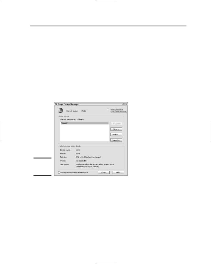
Sending a drawing to a plotter or to an electronic file for output can be challenging at first because of the number of options that AutoCAD and AutoCAD LT offer. AutoCAD offers a feature called the Page Setup Manager, which controls how the Model tab or layouts within a drawing are outputted.
The options that are part of a page setup are a subset of the options that are found in the Plot dialog box, which is covered in Chapter 3 of this minibook. Page setups help to provide consistency in the way your drawings are plotted. You can use the Page Setup Manager, shown in Figure 1-1, to create new page setups, import page setups from other drawing files, and assign page setups to layouts within the drawing.
Figure 1-1:
Page Setup
Manager.
Each layout in a drawing can have its own page setup, but to get the most flexibility out of using page setups, you should use one page setup across multiple layouts. Page setups are most commonly created in a drawing template (DWT) file, so they are available when a new drawing is created based on the drawing template. For more information on drawing templates, see the section “Creating a Good Foundation” in Chapter 1 of Book VIII.
Options of a page setup
From the Page Setup Manager, you create or select an existing page setup to modify. The steps for each process vary slightly, but in the end you end up in the Page Setup dialog box (see Figure 1-2). The Page Setup dialog box is