412 Using the Tool Palettes Window
Inserting hatches and loading linetypes
Hatch patterns can be dragged and dropped from DesignCenter. Use the Folders tab and browse to the folder that the Hatch Pattern (PAT) files are stored in. By default the hatch pattern (PAT) files that come with AutoCAD can be found in the folder C:\Documents and Settings\<user name>\ Application Data\Autodesk\AutoCAD 2007 (or AutoCAD LT 2007)\R17.0
(or R12.0)\enu\Support. User name varies based on what your Windows login is. Select the hatch pattern file, and then drag and drop the pattern from the Content Area into an enclosed area of your drawing. The enclosed area will be hatched. You can also load linetypes from a Linetype Pattern (LIN) file in the same way you drag and drop hatch patterns into a drawing.
Using the Tool Palettes Window
The Tool Palettes window is an interface that allows you to organize content on palettes of tools. These palettes of tools can be used to reference existing content such as blocks, xrefs, or images (AutoCAD only) and even custom commands. Tool palettes can be organized so that they can be shared across the company with other drafters, making it easy to develop and maintain CAD standards with them. The Tool Palettes window (see Figure 4-3) was originally introduced in AutoCAD 2004. The command TOOLPALETTES is used to display the Tool Palettes window.
Figure 4-3:
The Tool Palettes window.
414 Using the Tool Palettes Window
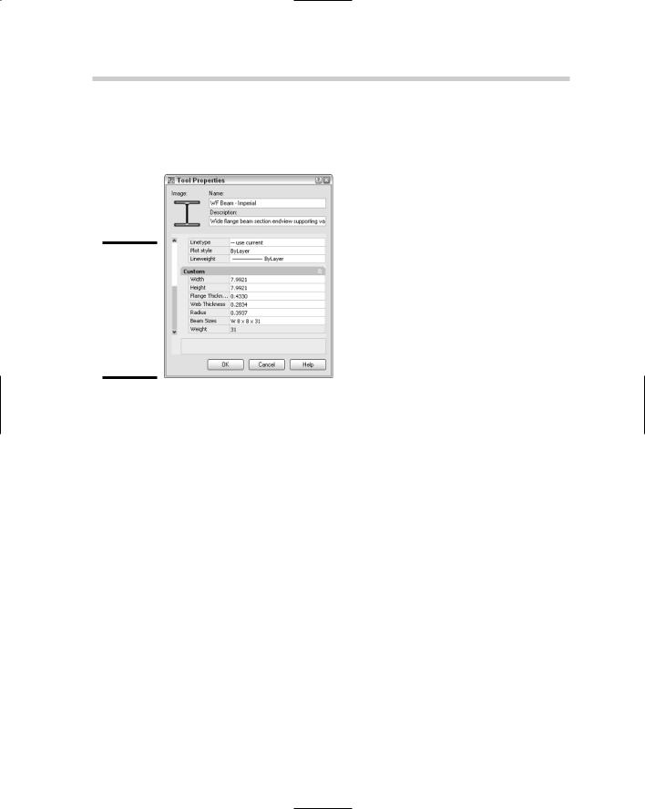
the tool. From the shortcut menu, select Properties to display the Tool Properties dialog box (See Figure 4-4). Change the properties as necessary and click OK to apply the changes.
Figure 4-4:
The properties of each tool on a tool palette can be tailored to a specific need.
Chapter 5: AutoCAD Utilities
In This Chapter
Filtering objects during selection
AutoCAD calculator
Auditing and recovering drawings
This chapter focuses on some of the utilities that AutoCAD offers to make you a more efficient drafter. Some of these utilities will help you precisely
select what you want to modify or remove from a drawing. We show you how to use the AutoCAD calculator for math calculations and unit conversions, and even to calculate points in a drawing.
At times, AutoCAD may not want to open a drawing or it may crash because of a bad drawing that was received from a contractor, a defect in the program, or even a Windows crash. In these cases, you may need to call upon a few utilities that allow you to recover and audit a drawing file that might contain errors.
Filtering Objects during Selection
In Book II, we talk about how to select objects using single and multiple object selection. Those options are great when you know the exact location of the objects that you want to modify, but what if you wanted to select all the circle objects on a specific layer. You can zoom and pan around the drawing to select each one and then modify the objects, but that can take some time. AutoCAD provides two commands, FILTER and QSELECT (Quick Select), to locate and select objects with specific property values.
Quick Select
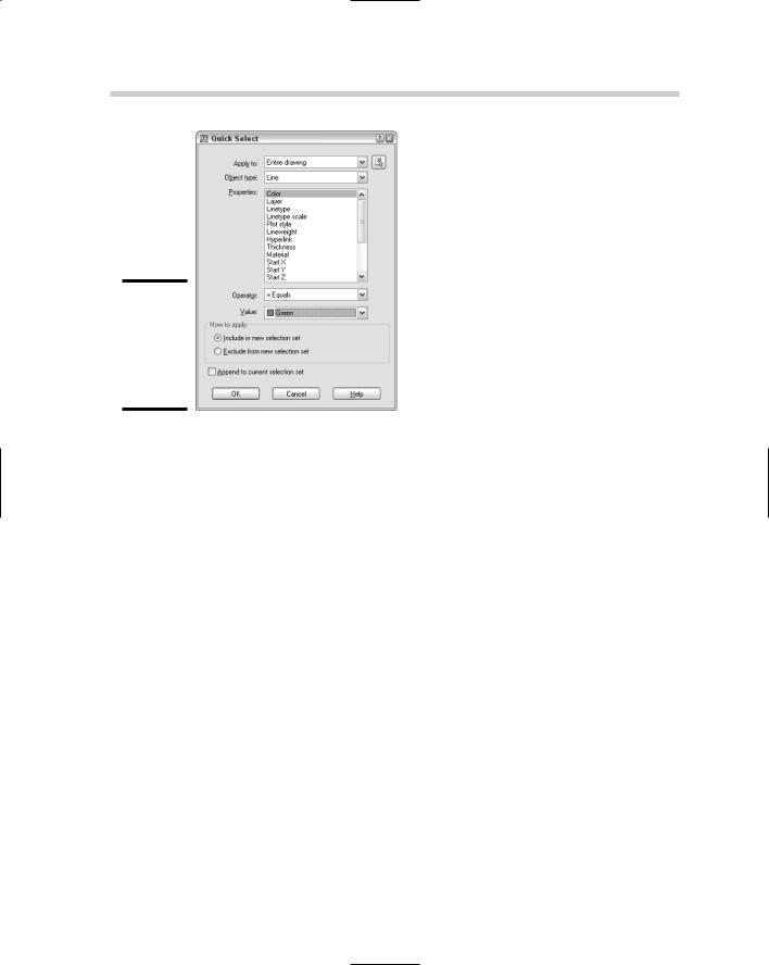
Quick Select was originally introduced with AutoCAD 2000 and has only seen minor changes. When you use QSELECT, the Quick Select dialog box appears (see Figure 5-1). From this dialog box, you can specify the objects to which you want to apply the filter, the type of object you want to find, and the property and value you want to use for the filter. You cannot run QSELECT during the execution of another command.
416 Filtering Objects during Selection
Figure 5-1:
Quick Select allows you to filter objects by
a single property.
To start the QSELECT command and display the Quick Select dialog box, use one of the following methods:
Tools menu. Choose Tools Quick Select.
Keyboard input. Type QSELECT and press Enter.
Properties palette. Click Quick Select.
To select all the blocks with a specific name, follow these steps:
1.Initiate the Quick Select command by using one of the previously described methods.
The Quick Select dialog box is displayed.
2.In the Quick Select dialog box, either select Entire Drawing from the Apply To drop-down list or click the Select Objects button.
If you click the Select Objects button, AutoCAD returns you to the drawing window where you are prompted to select the objects in the drawing to which you want to apply the filter. When you finish selecting objects, press Enter to return to the Quick Select dialog box.
3.Select Block Reference from the Object Type drop-down list.
Only the object types that are contained in the drawing appear in the Object Type drop-down list. To search for all objects in the drawing that are set to a color other than ByLayer, for example, select Multiple.
418 Filtering Objects during Selection
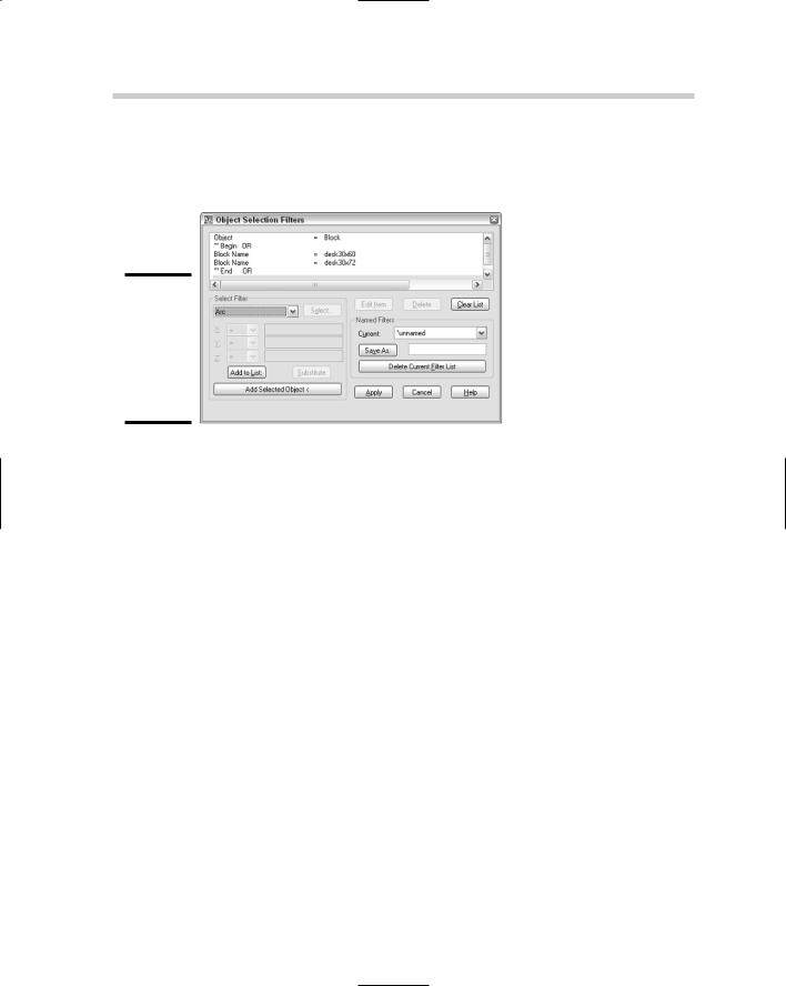
commands. To use the FILTER command transparently, you add an apostrophe in front of the command name. When you use the FILTER command, the Filter dialog box appears (see Figure 5-2).
Figure 5-2:
Filter is more complex, but with complexity comes more control.
The following procedure starts the FILTER command from the command line or the dynamic input tooltip and creates a filter that selects two different blocks based on their name and the layer they are on.
1.At the command prompt or the dynamic input tooltip, enter FILTER and press Enter.
The Filter dialog box appears (refer to Figure 5-2).
2.In the Filter dialog box, select Block from the drop-down list under the Select Filter area.
The drop-down list contains many common object types, group codes, and properties. You can add other properties to a filter by using the Add Selected Object button and then clicking the Delete button to remove the properties you are not interested in using with the filter.
3.Click Add to List.
The object type of Block is added to the list box at the top of the Filter dialog box.
4.Select ** Begin Or from the drop-down list under the Select Filter area. Click Add to List.
The items that begin with ** are group codes that allow you to build complex conditional statements that let you look for more than one object type or property at a time.

to third-party applications or even the calculator that comes with Windows. The problem was that these other calculators were not integrated into AutoCAD’s workflow. The command line-based calculator that comes with AutoCAD was not available in AutoCAD LT.
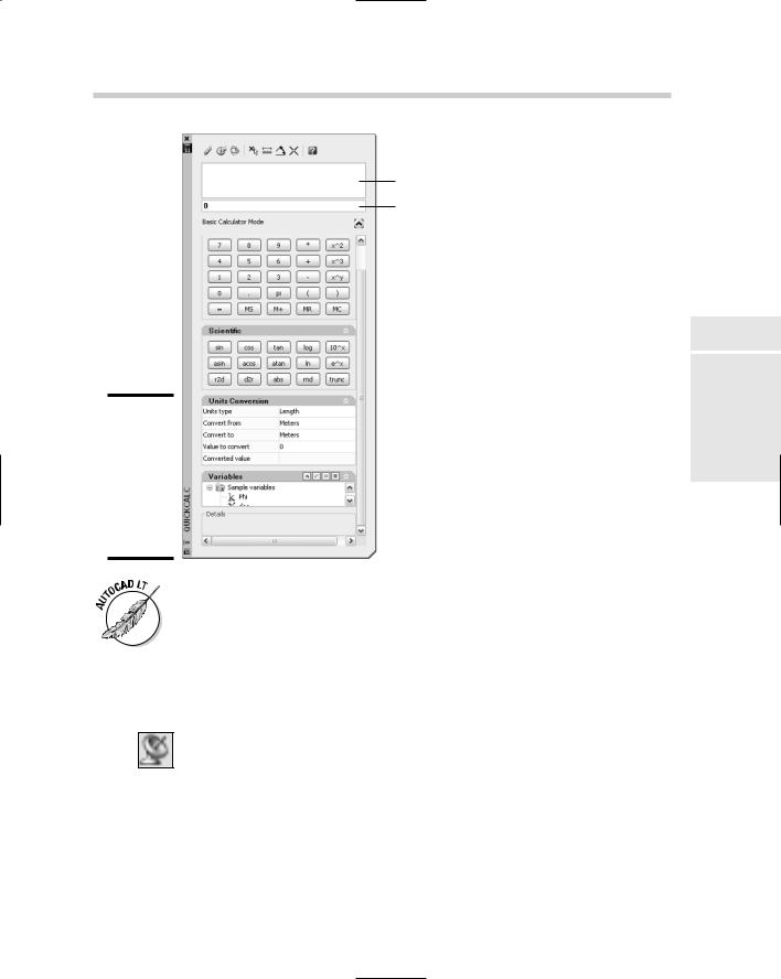
This all changed with the introduction of the new calculator command QUICKCALC in AutoCAD 2006. The QUICKCALC command could do everything that the legacy calculator could do but made it accessible through a graphical user interface. Along with the change to a graphical interface, the calculator was integrated into AutoCAD’s workflow by incorporating it into the Properties palette. The QUICKCALC command displays as either the QuickCalc palette (see Figure 5-3) or a dialog box. When a command is running in AutoCAD, QuickCalc is displayed as a dialog box instead of as a palette. Following is an overview of the types of expressions that QuickCalc offers.
Basic expressions. The Number Pad area offers most of the basic functionality for inputting basic math expressions such as adding, subtracting, and multiplying. The area contains numbers, parentheses for grouping expressions, and buttons for storing results in memory.
Scientific expressions. The Scientific area offers many common expressions related to scientific and engineering applications. These functions range from being able to calculate sine (sin) and cosine (cos) to convert radians to degrees (r2d) and degrees to radians (d2r). There are a total of 15 expressions that are available to you.
Unit conversion expressions. The Units Conversion area offers the ability to convert between different units of measure. QuickCalc allows you to convert units of measurement based on length, area, volume, and angular values.
Geometry and variable expressions. The Variables area and some of the tools along the top of the QuickCalc interface allow you to calculate values based on existing geometry in the current drawing. You can calculate the midpoint between two endpoints (mee) or the radius of a selected circle or arc (rad). You can create custom variables to store values that you might use often.