Добавил:
Опубликованный материал нарушает ваши авторские права? Сообщите нам.
Вуз: Предмет: Файл:

AutoCAD & AutoCAD LT All-In-One Desk Reference For Dummies (2006)

.pdf
Скачиваний:
90
Добавлен:
17.08.2013
Размер:
17.7 Mб
Скачать

402 Managing External References Outside of AutoCAD

2.In the Insert Object dialog box, select the Create from File option.

Create from File allows you to link to an existing file, whereas if you use Create New, you can’t link to the newly created file.

3.Select the Link check box.

This way, you keep a live link between the drawing and the selected file.

4.Click Browse and then select the word processor document or the file that you want to link to in your drawing. After you select the file, click Open to return to the Insert Object dialog box.

This way, you keep a live link between the drawing and the selected file.

5.Click OK and the document is placed into the drawing.

The document is placed in the upper-left corner of the drawing window.

Once an OLE object is placed in the drawing, you can modify it using many of the standard AutoCAD commands. If you want to edit the document, you can either double-click the object or select the object, right-click, and then choose an option from the OLE submenu. OLE objects cannot be rotated and are plotted best when using a system printer over a plotter.

Managing External References Outside of AutoCAD

AutoCAD comes with a utility called the Reference Manager. From the name, you can tell it must do something with external references. The Reference Manager allows you to modify the paths of external references that are attached to drawing files that you might create or receive from a contractor. This can make updating the locations of external references much easier than having to open each file one at a time and then update the external references location. The Reference Manager enables you to update the locations of xrefs, DWF underlays, raster images, plotter configurations, plot styles, shapes, and font files.

The Reference Manager is available only with AutoCAD and not with AutoCAD LT.

Follow these steps to access and edit dependency files of a drawing through the Reference Manager:

1.Click Start (Windows button) [All] Programs Autodesk AutoCAD

2007 and Reference Manager.

The Reference Manager dialog box appears (see Figure 3-10).

Managing External References Outside of AutoCAD 403

Red slash indicates missing references

Red exclamation indicates missing references

Figure 3-10:

Editing the dependencies of a drawing with the Reference Manager.

Pencil indicates reference path was edited

2.In the Reference Manager dialog box, click Add Drawings.

The Add Drawings dialog box appears.

3.In the Add Drawings dialog box, browse and select the drawing files for which you want to check or edit the dependencies. Click Open.

The Add Xrefs dialog box is displayed.

4.In the Add Xrefs dialog box, click Yes to load any external references that the drawing might have so that you can check those as well, or click No to not check external references.

The selected files are added to the tree view in the Reference Manager.

5.If a slash appears through the drawing icon in the tree view, the file has a problem. Select the drawing, and all the dependencies for the drawing appear in the list on the right.

6.Double-click the item that has a status of Not Found, indicated by a red exclamation point.

The Edit Selected Paths dialog box is displayed.

Book VI

Chapter 3

References External

404 Managing External References Outside of AutoCAD

7.In the Edit Selected Paths dialog box, click the ellipsis button to browse for the folder in which the file is located. Select the folder and click OK to return to the Edit Selected Paths dialog box.

The selected folder appears in the New Saved Path text box.

8.In the Edit Selected Path dialog box, click OK.

The item you double-clicked should now have the status of Resolved with a blue check mark in front of it with a pencil. The pencil shows which dependencies you have edited during the current session of the Reference Manager.

9.Keep editing any dependencies that need to be updated. When you are done updating the dependencies, click Apply Changes.

A Summary message box is displayed and provides some information about the number of host and reference drawings that have been updated and the number of files that couldn’t be updated. Click OK to close the Summary message box or click Details to try and figure out why a file couldn’t be updated.

10.Choose File Exit.

The Reference Manager dialog box closes. If you didn’t apply the changes, AutoCAD prompts you to do so. Click Yes to save the changes, No to discard the changes, or Cancel to stay in the Reference Manager dialog box.

Chapter 4: Organizing

Your Drawings

In This Chapter

Implementing standards

Using the Windows Clipboard

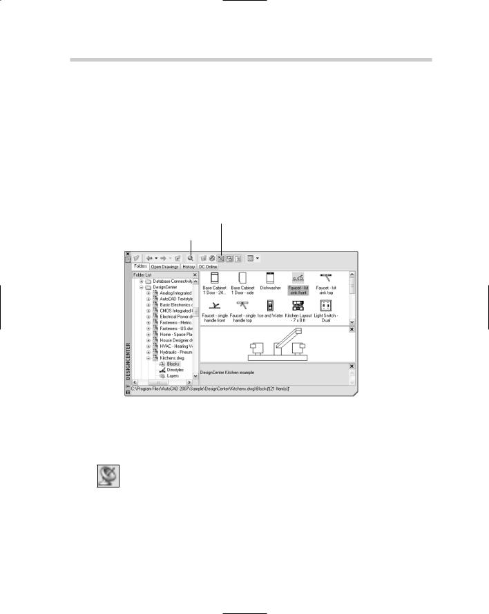
Using the DesignCenter

Understanding Tool Palettes

AutoCAD enables you to create content once and then reuse it in other drawings. Being able to create reusable content is one thing, but being

able to organize and manage all that reusable content is another. AutoCAD offers many ways to manage and organize usable content. You can use the Windows Clipboard to transfer content between two open drawings or another Windows-based application. It is not always efficient to open a drawing just to access its content, so AutoCAD comes with two interfaces to help you access content from drawings that might be saved locally on your computer or on a network drive. These two interfaces are called DesignCenter and Tool Palettes.

Why Bother to Organize Drawings?

It takes time to develop accurate drawings, but you can make the process go faster and faster over time. By creating good CAD standards and highquality reusable content, you can improve your efficiency. We talk about CAD standards in detail in Book VIII, but for now, we address the importance of properly naming and managing reusable content.

It’s all in the name

Many things in AutoCAD that can be reused are given a name, such as a text style, layer, or even a layout. It is a good idea to keep these names meaningful so that you or anyone else looking at the name can decipher its intended purpose. At times this can cause problems; obviously, if you are sharing drawings with other clients, you will most likely both have a title block in your drawings. It is a good idea to prefix or suffix your blocks with text that denotes scale, units, or even a company identifier to avoid problems with duplicate names. Not only will this avoid problems when exchanging drawings with other contractors, it will also help you when searching for named objects in your own drawings.

406 Using the Windows Clipboard

An example of creating a uniquely named block to be used for an A-sized title block by company ABC might be TitleBlock-A-ABC. Now this is only a recommendation that we have observed through the years of exchanging drawings with other companies. There is nothing wrong with calling your title block TB or TitleBlock. No matter how you decide to name objects such as layers, text styles, and layouts to name a few, it is a good idea to develop a naming convention and make sure everyone in your company follows it. Doing so makes managing CAD drawings much easier.

Using the Windows Clipboard

AutoCAD is a Windows-based program, and like most Windows-based programs, AutoCAD is capable of using the Windows Clipboard to exchange information between two programs. The two programs may be two instances of AutoCAD, or AutoCAD and another Windows-based program, or even two different drawing windows. You can copy or cut objects from a drawing and place them on the Windows Clipboard. From there, you can paste them into AutoCAD or another application. You can also copy information from other Windows-based programs and paste that information into an open drawing.

Copying objects from a drawing

You can copy objects to the Windows Clipboard in a couple of ways. You are able to do a basic copy of select objects in the drawing window through the use of the COPYCLIP command, the standard keyboard shortcut of CTRL+C, or by clicking the Copy button from the Standard toolbar. When you use COPYCLIP on objects in the drawing, AutoCAD copies the objects to the Windows Clipboard and calculates an insertion point to use when pasting the copied objects from the Clipboard. The insertion point is based on

the lower-left corner of the extents of the selected objects, also known as the bounding box of the selected objects.

If you want control over choosing the insertion point of the copied objects, you can use the command COPYBASE or the keyboard shortcut Ctrl+Shift+C. If you are not concerned with accurate placement, you can copy objects within the same drawing or between two drawings by dragging them onscreen. If you select the objects without any command running and start dragging the objects, they are moved if you released the mouse button, but if you hold the Ctrl key while dragging the objects, a plus sign appears near the crosshairs, allowing you to copy the objects instead of moving them.

Cutting objects from a drawing

Copying objects in your drawing or between files using the Windows Clipboard is nice, but at times you might just want to cut (or move) objects. To cut objects from one drawing and place them onto the Windows Clipboard, use

AutoCAD DesignCenter 407

the CUTCLIP command, the standard keyboard shortcut of CTRL+X, or the Cut button from the Standard toolbar. When you use CUTCLIP on objects in a drawing, AutoCAD moves the objects to the Windows Clipboard and calculates an insertion point to use when pasting the copied objects from the Clipboard. The insertion point is based on the lower-left corner of the extents of the selected objects, also known as the bounding box.

AutoCAD does not provide a cut operation that is similar to the COPYBASE command. You can cut objects within the same drawing by dragging them on-screen. If you select the objects without any command running and start dragging the objects, they are moved when you release the mouse button.

Pasting objects into a drawing

After you place objects on the Windows Clipboard, you can paste them into a drawing or another Windows-based application. The pasted results vary based on the application into which you are pasting the objects. You can choose from three options to paste between drawings. The first is a standard paste, which doesn’t give you much control over the placement of the objects you are pasting. This option of paste is started by using the PASTECLIP command, the standard keyboard shortcut Ctrl+V, or the Paste button from the Standard tool. If you used the COPYBASE command, you already know the insertion point of the objects being pasted back into AutoCAD. If you used COPYCLIP or CUTCLIP, you don’t know the insertion point until you begin pasting the objects into the drawing.

The second option for pasting is to paste objects to their original coordinates where they were before they were copied or cut to the Windows Clipboard. This option of paste is started by the PASTEORIG command. This can be useful when copying and pasting title blocks between layouts or drawings. The final option of pasting content between drawings is the ability to paste the contents of the Windows Clipboard as a block. This option of paste is started by the PASTEBLOCK command or the keyboard shortcut Ctrl+Shift+V.

If you are pasting objects from other Windows-based applications, you may want to use the PASTESPEC command. Using this command, you can define how objects on the Windows Clipboard are pasted into AutoCAD. For example, if you copy cells in a spreadsheet program to the Windows Clipboard, you can paste the copied cells into AutoCAD as a table object.

AutoCAD DesignCenter

Book VI

Chapter 4

OrganizingDrawings

Your

The AutoCAD DesignCenter is an interface that allows you to perform data mining. Data mining is a popular buzz phrase in the marketing world, but you

408 AutoCAD DesignCenter

can do it with AutoCAD drawings, as well. Data mining allows you to locate information that is of importance to you and reuse it. In marketing, data mining might determine whether a product will sell; in AutoCAD, you are mining your data for reusable content in the form of drawings, images (AutoCAD only), layers, blocks, and other named objects.

DesignCenter (see Figure 4-1) was originally introduced in AutoCAD 2000. It allows you to access content that is stored in drawing, hatch pattern, linetype pattern, and image (AutoCAD only) files, and reuse the content in any drawing that you have open. The command ADCENTER is used to display the DesignCenter.

Tree View Toggle

Search


Content area


Figure 4-1:


DesignCenter


allows you


Preview


to mine your


drawings for


reusable


content.


To start the ADCENTER command and display the DesignCenter palette, use one of these methods:

Tools menu. Choose Tools Palettes DesignCenter.

Standard toolbar. Click the DesignCenter button on the Standard toolbar.

Keyboard input. Type ADCENTER and press Enter.

Command alias. Type ADC and press Enter.

Shortcut Key. Press the key combination CTRL+2.

AutoCAD DesignCenter 409

Locating resources in drawings

By using DesignCenter, you can access content in a number of ways. You can access content that has or has not been opened in AutoCAD. The content can be stored locally on your computer, on a network, or even in an online library of blocks. In order to locate information by browsing, you use one of the four tabs along the top of the DesignCenter palette. These four tabs are as follows:

Folders. Allows you to browse your local and network drives for drawing or image (AutoCAD only) files.

Open Drawings. Allows you to access any drawing files currently open in AutoCAD.

History. Allows you to access any drawing files that have been recently open during the current AutoCAD session.

DC Online. Allows you to access blocks from an online portal hosted by Autodesk. The online portal has many different 2D and 3D blocks available for use in your drawings, and they are organized into categories to make it easier to find which blocks you might be interested in.

Browsing for content is not always the most efficient way to find something, especially when you don’t remember exactly which drawing file something might be located in. Well, you are in luck; DesignCenter has a search feature that allows you to look for drawings that contain specific content. Maybe there is a drawing with a block in it that you want to use in your current drawing; it is possible to search for that block based on a wild character string. Click the Search button on the DesignCenter toolbar to display the Search dialog box (see Figure 4-2).

Figure 4-2:

Using the

Search feature of Design Center.

Book VI

Chapter 4

OrganizingDrawings

Your

410 AutoCAD DesignCenter

To search for a block, follow these steps:

1.Use any of the previously mentioned methods to initiate the ADCENTER command.

The DesignCenter palette appears.

2.In the DesignCenter palette, click Search.

The Search dialog box appears.

3.In the Search dialog box, select Blocks from the Look For drop-down list.

Normally, you would select the type of content that you want to search for from the Look For drop-down list. This controls many of the options in the Search dialog box.

4.Either select a folder from the In drop-down list to scan for content, or click Browse and browse to the location where you want to start scanning for content.

If you click Browse, the Browse for Folder dialog box appears. Browse to the folder you want to select in the Browse for Folder dialog box, select the folder, and then click OK. You can also uncheck the Search Subfolders option to limit the scanning for the content in the folder that you select.

5.In the Search for the Name text box, enter the block name for which you want search.

You can use wild characters to help broaden the search if you don’t quite remember the name of the block. You can use a pound (#) symbol to replace a single character or an asterisk (*) to replace a range of characters.

6.Click Search Now.

The search results appear at the bottom of the dialog box.

7.Click Stop to end the search early if it has found what you wanted, or wait until the search has completed.

8.Right-click the content you want to place in the drawing or load into the Content Area of DesignCenter.

Based on the content for which you were searching, the options vary on the right-click menu.

9.Click the Close button (“X”) on the DesignCenter to close it, or leave it displayed so you can access it later if necessary.

AutoCAD DesignCenter 411

Adding resources to drawings

After you find the content you want by using one of the four tabs or the Search dialog box, you can get it into a drawing. Position the DesignCenter so that you can see the drawing window that you want to drop the content into and then select the icon that represents the content from the Content Area. Press and hold the left mouse button over the icon and drag it over the drawing window. Release the mouse button to insert or add the content to the drawing window. AutoCAD ignores duplicate named objects.

To add a block to a drawing, follow these steps:

1.Use any of the previously mentioned methods to initiate the ADCENTER command.

The DesignCenter palette is displayed.

2.In the DesignCenter palette, click the Folders tab.

The Folders tab and Folders List tree view appear. If they do not, click the Tree View Toggle button along the top of the DesignCenter palette.

3.In the Folders List tree view, browse to the folder that contains the drawing with the block you want to add to your drawing.

The Folders List tree view is similar to Windows Explorer.

4.When you locate the drawing that contains the block you want to place in your drawing, select the drawing under the Folder List tree view.

The available named objects are displayed in the content area to the right of the Folder List tree view.

5.In the Content Area, double-click the Blocks icon.

Icons for the blocks in the drawing are displayed in the Content Area.

6.Right-click over the icon for the block that you want to insert into the drawing, and select Insert Block.

The Insert dialog box appears.

7.In the Insert dialog box, complete the options and click OK to place the block. Don’t forget to follow the command prompts.

You could have also dragged and dropped the block from the Content Area into a drawing, but it doesn’t give you as much control over its placement.

8.Click the Close button (“X”) on the DesignCenter to close it, or leave it displayed.

Book VI

Chapter 4

OrganizingDrawings

Your