

AutoCAD & AutoCAD LT All-In-One Desk Reference For Dummies (2006)
.pdf392 DWG References
If you use demand loading, you can take advantage of indexing in your drawing file. Indexing allows AutoCAD to locate specific objects and layers in a drawing that is being referenced. AutoCAD offers two types of indexing, called spatial and layer. We talk more about spatial and layer indexing in Book VIII.
Binding an xref
An xref can be entirely bound to its parent (or host) drawing. You can also bind select named styles to an xref’s parent drawing. To integrate all the objects and styles in an xref, right-click the xref that you want to bind in the External References palette and select Bind from the shortcut menu. The Bind Xrefs dialog box appears, which allows you to specify one of the two bind types: Bind or Insert.
If you choose Bind for the bind type, the named object in the xref is bound with the name structure of <file name>$#$<symbol name>. For example, if you bind an xref with the filename Grid Plan that has a layer called Grid into a drawing, it is bound with the name Grid Plan$0$Grid. If you choose Insert for the bind type, the same layer name as previously mentioned is just Grid. The named objects are merged cleanly into the existing named objects of the parent drawing when the Insert bind type is used.
You can also bind a named object and not any of the objects in the xref by using the XBIND command. The XBIND command displays the Xbind dialog box (see Figure 3-5). In the Xbind dialog box, expand the xref under the Xrefs area and expand each of the named object tables that you want to bind into the parent drawing. Select the named object and click the Add button. The named object is added to the Destinations to Bind area. Click OK to bind the named objects to the parent drawing.
Figure 3-5:
Xbind allows you to bind selected named objects into the parent drawing.
Raster Images 393
Raster Images
AutoCAD allows you to reference many different kinds of raster images into your drawing files. You may want to reference a raster image that holds a company logo or maybe it is a rendered image of a part in a drawing. Raster images are files that are made up of a series of dots, which are referred to as pixels. AutoCAD and AutoCAD LT are vector-based programs, which means they store objects in the form of coordinate values and properties to regenerate the objects when the file is opened, viewed, or plotted. Raster images are referenced into a drawing the same way that you reference a drawing file. Unlike xrefs, raster images cannot be bound to a drawing.
AutoCAD LT does not support the attaching of raster images in the External References palette. If you open a drawing that was created in AutoCAD, you can work with the raster image in the External References palette.
Attaching a raster image
To attach raster images to a drawing, you use the External References palette or the IMAGEATTACH command. During the attachment process, you need to determine where in the drawing the image should be placed, its scale and rotation, and the path type that you want to use. When an image is scaled, it can appear grainy on-screen; when plotted, the graininess is due to how the image was created and its DPI (dots per inch). The greater the DPI, the larger the image can be scaled before it starts to appear grainy.
To start the IMAGEATTACH command and display the Image dialog box, use one of these methods:
Insert menu. Choose Insert Raster Image Reference.
Reference toolbar. Click the Attach Image button on the Reference toolbar.
Insert toolbar. Click the Attach Image button on the Insert toolbar.
Keyboard input. Type IMAGEATTACH and press Enter.
Command alias. Type IAT and press Enter.
Right-click the File References area in the External References palette.
From the shortcut menu, select Attach Image.
Book VI
Chapter 3
References External
394 Raster Images
To attach a raster image to your drawing, follow these steps. For more information on some of the options in the Image dialog box, see the section “DWG References.”
1.Use any of the previously mentioned methods to initiate the IMAGEATTACH command.
The Select Image File dialog box appears.
2.In the Select Image File dialog box, browse to the raster image file that you want to attach and select it. Use the Files of Type drop-down list to filter the displayed files in the dialog box. Click Open.
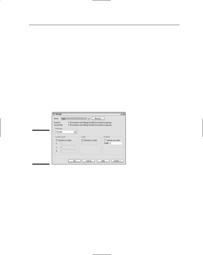
The Select Image File dialog box closes, and the Image dialog box (see Figure 3-6) is displayed. The filename and path you selected appear in Found In and Saved Path. The drop-down list allows you to select a previously attached raster image file, and Browse allows you to specify a different raster image file to reference.
Figure 3-6:
Attaching a raster image reference is similar to attaching an xref.
3.In the Image dialog box, click Details to display additional information about the image.
The Image Information area provides you feedback on how the image will be scaled upon being inserted. AutoCAD automatically calculates the number of pixels by the current units to determine the size of the image when it is inserted. The current AutoCAD units are determined by the setting under the Insertion Scale area of the Units dialog box.
4.In the Path Type area, specify the type of pathing that the raster image should maintain when attached.
5.In the Insertion Point area, specify how and where the image should be inserted.
6.In the Scale area, specify how the image should be scaled.
Raster Images 395
7.In the Rotation area, specify how the image should be rotated.
8.Click OK.
The Image dialog box closes and you are returned to the drawing window. The IMAGEATTACH command may still be running depending on whether you checked any of the Specify On-Screen options for the insertion point, scale, or rotation. Specify the prompts as required. Here are the possible prompts:
Specify insertion point <0,0>:
Specify scale factor or [Unit] <1>:
Specify rotation angle <0>:
Clipping a raster image
Like xrefs, raster images can be clipped to show only part of the image. Only showing what is necessary in the drawing can help to save time when you need to regenerate the drawing during zooming because only the necessary section of the drawing is displayed, especially if a large image is attached. The IMAGECLIP command controls the clipping boundary of a raster image. The IMAGECLIP command has the same options as the XCLIP command, with the exceptions of Generate Polyline and Select Polyline.
To start the IMAGECLIP command, follow one of these methods:
Modify menu. Choose Modify Clip Image.
Reference toolbar. Click the Clip Image button on the Reference toolbar.
Keyboard input. Type IMAGECLIP and press Enter.
Command Alias. Type IC and press Enter.
Select a raster image and right-click. From the shortcut menu, select Image and then Clip.
Clipping a raster image reference
Here’s how to clip a raster image based on a rectangular boundary:
1.Use any of the previously mentioned methods to initiate the IMAGECLIP command.
2.At the command prompt, select the raster image you want to clip and press Enter to end selecting objects.
3.Press Enter to accept the default option of creating a new boundary or select one of the other available options.
Book VI
Chapter 3
References External
396 Raster Images
4.Press Enter to accept the default option of creating a rectangular clipping boundary or select the other available option.
5.Specify the first corner and then the opposite corner of the rectangular clipping boundary. The points should be outside the area of the image you want left visible.
The boundary that is displayed before and after you use the IMAGECLIP command can be controlled by choosing Modify Object Image Frame (which starts the IMAGEFRAME command). The toggle controls all image frames. By default the frame is displayed and plotted. You have three options to control how the frame should be displayed: 0 hides the frame from display and plotting, 1 displays the frame and is plotted, and 2 displays the frame and is not plotted.
You can use the IMAGEFRAME command to lock images so they can’t be selected by using a value of 0.
Editing a clipped image
You can modify the clipped boundary of a raster image by running the IMAGECLIP command again or selecting the clip boundary and using grips
to modify what is displayed. You can use the IMAGECLIP command to replace the clipping boundary that is already assigned to the image, remove the clip boundary, or turn the clip boundary on or off. IMAGEFRAME must be set to a value of 1 or 2 in order to select the image so the clipped boundary can be modified.
Controlling the appearance of a raster image
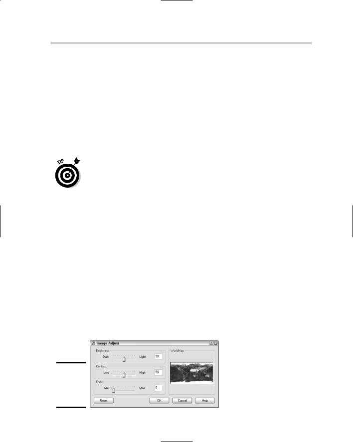
AutoCAD allows you to tweak an image after it is attached to a drawing. You can alter the appearance of the image by changing its level of brightness, contrast, or fade. You can use the Properties palette or the IMAGEADJUST command. The IMAGEADJUST command displays the Image Adjust dialog box (see Figure 3-7) for controlling the values, and as the values are changed, the preview in the dialog box is updated. If you use the Properties palette, the changes are dynamically displayed in the drawing window.
Figure 3-7:
Adjusting the appearance of
an image.
DWF Underlays 397
If you have an image that is fairly large in size, it can slow down the regeneration process of the drawing. You can clip the image, but this is not always an option depending on the drawing you are working on. The command IMAGEQUALITY allows you to control the quality of the image that you see on-screen. You can choose from either High or Draft; selecting Draft can help to decrease the amount of time it takes to regenerate the display of a drawing. This setting does not affect plotting because plotting is always done as High. If your attached image type supports transparency, you can control whether the image is displayed transparent so objects beneath it are displayed. The command TRANSPARENCY allows you to toggle transparency for an image on or off.
DWF Underlays
Design Web Format (DWF) files are commonly used for exchanging drawings in a secure electronic format that non-CAD users can view and print using
a free viewer, such as Autodesk DWF Viewer, or view, print, and perform markups of drawings with Autodesk DWF Composer. DWF and drawing files are vector based files unlike raster images, which are made up of pixels. When a DWF file is attached to a drawing, it is known as an underlay. Since a DWF file is a vector-based file, AutoCAD allows you to snap to the objects that are referenced in. A DWF file cannot be bound to a drawing file, which helps to maintain the files security. We talk more about DWF files in Book VIII.
Attaching a DWF underlay
To attach DWF files to a drawing, you use the External References palette or the DWFATTACH command. When you attach a DWF file, you need to determine where in the drawing the DWF underlay should be placed, its scale and rotation, the path type that should be used, and which one of the sheets from the DWF file is being referenced. Attaching DWF files is limited to 2D DWF files only; if you select a 3D DWF file, AutoCAD informs you that the selected file doesn’t contain any sheets that can be attached. Layer information is not imported into the drawing when a DWF file is attached; all the objects in the DWF underlay are placed on the current layer.
To start the DWFATTACH command and display the Attach DWF Underlay dialog box, use one of the following methods:
Insert menu. Choose Insert DWF Underlay.
Insert toolbar. Click the Insert a DWF Underlay button on the Insert toolbar.
Book VI
Chapter 3
References External
398 DWF Underlays
Keyboard input. Type DWFATTACH and press Enter.
Right-click the File References area in the External References palette.
From the shortcut menu, select Attach DWF.
To attach a DWF file, use the following steps. For more information on some of the options in the Attach DWF Underlay dialog box, see the section “DWG References.”
1.Use any of the previously mentioned methods to initiate the DWFATTACH command.
The Select DWF File dialog box appears.
2.In the Select DWF File dialog box, browse to and select the DWF file that you want to attach. Click Open.
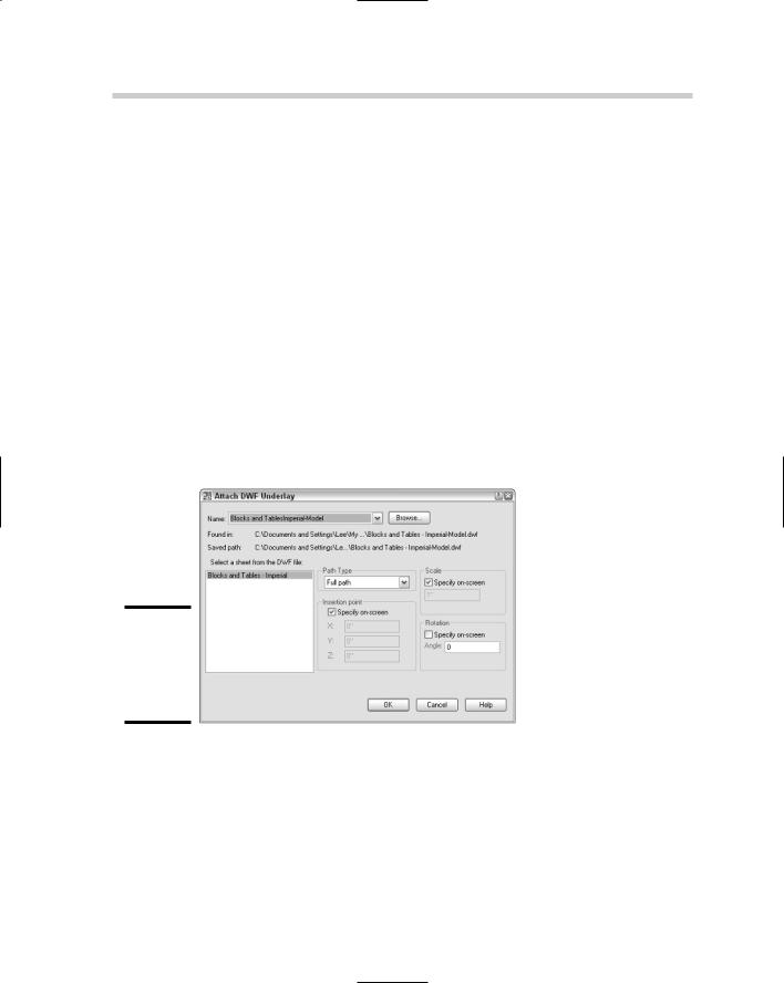
The Select DWF File dialog box closes, and the Attach DWF Underlay dialog box (shown in Figure 3-8) is displayed. The selected filename and path are displayed under Found In and Saved Path. The drop-down list allows you to select a previously attached DWF file, and Browse allows you to specify a different DWF file to reference.
Figure 3-8:
Attaching a DWF file is similar to attaching an xref.
3.In the Attach DWF Underlay dialog box, select a listed sheet in the Select a Sheet from the DWF File list box.
The selected sheet is highlighted and is the one that is attached.
4.In the Path Type area, specify the type of pathing that the raster image should maintain when attached.
5.In the Insertion Point area, specify how and where the image should be inserted.
DWF Underlays 399
6.In the Scale area, specify how the image should be scaled.
7.In the Rotation area, specify how the image should be rotated.
8.Click OK.
The DWF Attach Underlay dialog box closes, and you are returned to the drawing window. The DWFATTACH command may still be running depending on whether you checked any of the Specify On-Screen options for the insertion point, scale, or rotation. Specify the prompts as required. Here are the possible prompts:
Specify insertion point:
Specify scale factor or [Unit] <1.0000>:
Specify rotation angle <0>:
Only one sheet from the DWF file can be attached at a time. If you need to attach multiple sheets from the DWF file, you need to repeat the preceding steps for each of the sheets that you want to attach.
The system variable DWFOSNAP controls whether object snaps can be used on objects that are part of the DWF underlay. By default, you can use object snaps with DWF underlays. Set the system variable DWFOSNAP to a value of 0 (zero) to disable the use of object snaps with DWF underlays, or 1 to enable the use of object snaps with DWF underlays.
Clipping a DWF underlay
DWF underlays can be clipped just like xrefs to show only part of the referenced sheet. The DWFCLIP command is used to control the clipping boundary of a DWF underlay. The DWFCLIP command has the same options as the XCLIP command, with the exceptions of Generate Polyline and Select Polyline.
To start the DWFCLIP command, use one of the following methods:
Keyboard input. Type DWFCLIP and press Enter.
Select a DWF underlay and right-click. From the shortcut menu, select DWF Clip.
Clipping a DWF reference
To start the DWFCLIP command and clip a DWF underlay based on a rectangular boundary, follow these steps:
1.Use any of the previously mentioned methods to initiate the DWFCLIP command.
2.Press Enter to accept the default option of creating a new boundary or select one of the other available options.
Book VI
Chapter 3
References External

400 Draw Order
3.Press Enter to accept the default option of creating a rectangular clipping boundary or select the other available option.
4.Specify the first corner and then the opposite corner of the rectangular clipping boundary. The points should be outside the area you want left visible of the DWF underlay.
You can control the boundary that is displayed before and after you use the DWFCLIP command by using the DWFFRAME system variable. The DWFFRAME system variable controls the display of the frames for all DWF underlays in a drawing. By default the frame is displayed and not plotted. You have three options to control how the frame should be displayed: 0 hides the frame from display and plotting, 1 displays the frame and is plotted, and 2 displays the frame and is not plotted.
Editing a DWF reference
You can modify the clipped boundary of a DWF underlay by running the DWFCLIP command again, or by selecting the clip boundary and using grips to modify what is displayed. You can use the DWFCLIP command to replace the clipping boundary that is already assigned to the DWF underlay, remove the clip boundary, or turn the clip boundary on or off.
Controlling the appearance of DWF underlay
AutoCAD allows you to adjust the appearance of the objects of a DWF underlay by changing its level of brightness, contrast, or fade. You can use the Properties palette or the DWFADJUST command. The DWFADJUST command works from the command line only, unlike the IMAGEADJUST command. If you use the Properties palette, the changes are dynamically displayed in the drawing window.
Draw Order
Draw order determines how objects are displayed on-screen and how they are plotted. When you draw new objects, they are placed at the top of the draw order and therefore appear above other objects in the drawing. AutoCAD provides several different commands that allow you to control the draw
order of objects in the drawing. You use the commands DRAWORDER and TEXTTOFRONT to help control the order in which objects are displayed. For example, you can use the DRAWORDER commands to display objects on top of a raster image or text in front of other objects when it is assigned a background mask so that it hides the objects that need to be masked out below the text.

Object Linking and Embedding (OLE) 401
The DRAWORDER command has four options and allows you to bring objects all the way to the front, send them all the way to the back, or bring them up in front or behind selected objects. The TEXTTOFRONT command allows you to quickly bring all text and/or dimensions to the front. If you are using fills or background masks with your text and dimensions, you want to make sure that they are all the way at the top of the display order to make sure that all objects below them are properly masked.
Object Linking and Embedding (OLE)
Object linking and embedding — or OLE as it is often referred to — allows you to place information from one Windows-based application into another while being able to keep the ability to edit the information using the original application. For example, you can link information from a spreadsheet and have it displayed in AutoCAD. Then if the spreadsheet is updated, the changes are reflected in AutoCAD the next time the drawing file is loaded. You use
the INSERTOBJ command to insert and link a document into a drawing. The INSERTOBJ command displays the Insert Object dialog box (see Figure 3-9).
Figure 3-9:
Attaching a file to a drawing other than a drawing, DWF file, or image.
To start the INSERTOBJ command and display the Insert Object dialog box, use one of the following methods:
Insert menu. Choose Insert OLE Object.
Insert toolbar. Click the OLE Object button on the Insert toolbar.
Keyboard input. Type INSERTOBJ and press Enter.
To start the INSERTOBJ command and link a word processor document, follow these steps:
1.Use any of the previously mentioned methods to initiate the INSERTOBJ command.
The Insert Object dialog box appears.
Book VI
Chapter 3
References External