

AutoCAD & AutoCAD LT All-In-One Desk Reference For Dummies (2006)
.pdf382 Working with External References
Working with External References
In past releases of AutoCAD, you had to use several dialog boxes to manage the various types of external references. AutoCAD 2007 introduces a single interface that allows you to manage DWG references, DWF underlays, and raster image references (AutoCAD only). This single interface is called the External References palette (see Figure 3-1). The External References palette allows you to attach, detach, reload, and unload the various types of references available in AutoCAD. The EXTERNALREFERENCES command is used to display the External References palette.
Along the top of the palette you are able to access tools for attaching an external reference, reloading external references, or launching Help. The File References area is the main portion of the palette that displays which files are currently referenced in the drawing. This area allows you to control how you view the referenced files in the palette, either in the default list view, which just shows which files are referenced, or the tree view, which displays the relationship between the parent (or host) drawing and all the files that are currently being referenced. The lower portion of the palette displays details about a selected reference, or a preview of the selected reference.
Figure 3-1:
The External References palette is used to manage attached DWG, DWF, and raster image files.
To start the EXTERNALREFERENCES command and display the External References palette, follow one of the following methods:
Tools menu. Choose Tools Palettes External References.
Insert menu. Choose Insert External References.
DWG References 383
Reference toolbar. Click the External References button on the Reference toolbar.
Keyboard input. Type EXTERNALREFERENCES and press Enter.
Command alias. Type ER and press Enter.
DWG References
AutoCAD allows you to reference an entire drawing file into another drawing. The drawing that is being referenced is referred to as an xref, which is short for external reference. When a drawing is referenced into another drawing, all the styles contained in the file are maintained, so the drawing looks just like it would if you opened the file. Attaching an xref is similar to a block with the exception of needing to specify an attachment and path type. There are two different attachment types for xrefs: attachment and overlay. The attachment types control how the xref is displayed and used for certain operations. The following list explains the two attachment types:
Attachment. Attachments are used for visual reference and allow you to snap to objects contained in the xref. Attachments are plotted.
Overlay. Overlays are used for visual reference and allow you to snap to objects contained in the xref, but if the file that contains an overlay is referenced into another drawing, AutoCAD does not load or display the overlay.
When an xref is attached to a drawing, you can control how AutoCAD stores the pathing information to the source file that is associated with the xref. There are three different path types for Xrefs: Full path, Relative path, and No path. Here is a description of the three path types:
Full path. The absolute path to the file is maintained, which includes the drive letter and all folders. This option is the least flexible as it requires the drawings to be placed in specific locations in order for AutoCAD to find them.
Relative path. Only the path relative to the parent (or host) drawing is maintained with the xref. This option is more flexible than Full path if your xrefs are stored in subfolders above or below the parent drawing.
No path. No path information is maintained with the xref. AutoCAD looks in the parent (or host) drawings folder for the xrefs. This option is the easiest to maintain because it looks for the xrefs in the same folder as the parent drawing. Even though it is the easiest to use, it doesn’t allow for much in the form of organization as the other two options.
Book VI
Chapter 3
References External

384 DWG References
When AutoCAD loads an xref, it first looks in the folder that is specified by the path type. From there, it looks in the following locations in the listed order:
Current folder of the parent (or host) drawing
Project search paths specified under the Project Files Search Path on the Files tab of the Options dialog box, or the PROJECTNAME system variable (AutoCAD only)
Support search paths specified under Support File Search Path on the Files tab of the Options dialog box
The path specified in the Start-in property of the shortcut used to start AutoCAD or AutoCAD LT
Attaching an xref
Xrefs are attached to a drawing through the External References palette or the XATTACH command. During the attachment process, you need to determine the type of attachment that should be used, where in the drawing the xref should be placed, its scale and rotation, and the path type that should be used. When the xref is attached to a file, all its named objects are suffixed with a “|<filename>”. For example, if a drawing file named 1234 - Floor Plan contained a layer called TitleBlock, and the file was referenced into another drawing, the layer would look like TitleBlock|1234 - Floor Plan.
To start the XATTACH command and display the Select Reference File dialog box, follow one of these methods:
Insert menu. Choose Insert DWG Reference.
Reference toolbar. Click the Attach Xref button on the Reference toolbar.
Insert toolbar. Click the Attach Xref button on the Insert toolbar.
Keyboard input. Type XATTACH and press Enter.
Command alias. Type XA and press Enter.
Right-click over the File References area in the External References palette. From the shortcut menu, select Attach DWG.
Here’s how to attach a DWG reference.
1.Initiate the XATTACH command by using one of the methods described in the preceding list.
The Select Reference File dialog box is displayed.
2.In the Select Reference File dialog box, browse to and select the drawing file that you want to attach. Click Open.
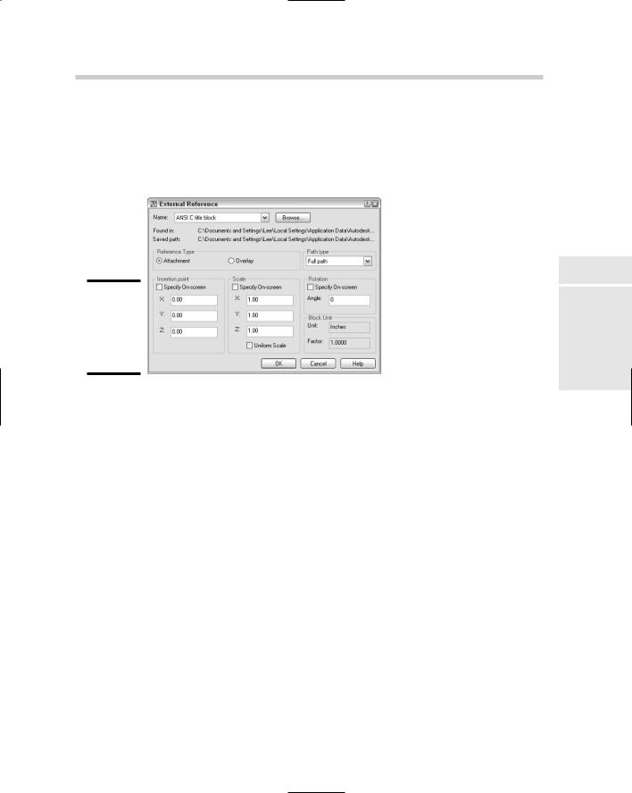
Figure 3-2:
Attaching an xref is similar to inserting a block.
DWG References 385
The Select Reference File dialog box closes, and the External Reference dialog box appears (see Figure 3-2). The selected filename and path are displayed under Found In and Saved Path. The drop-down list allows you to select a previously attached DWG file, and Browse allows you to specify a different DWG file to reference.
Book VI
Chapter 3
References External
3.In the External References dialog box under the Reference Type area, specify the type of attachment you want the xref to be.
You can select from either Attachment or Overlay.
4.Under the Path Type area, specify the type of pathing that the xref should maintain when attached.
You can select from either Full path, Relative path, or No path. If you want to use the Relative Path option, the drawing that the xref is being attached to must be saved first.
5.Under the Insertion Point area, either check or uncheck the Specify On-Screen option. If it is unchecked, enter the coordinate value for the insertion point of the block in the X, Y, and Z text boxes.
If Specify On-Screen is checked, you are prompted for the insertion point of the xref after you click OK to close the External Reference dialog box.
6.Under the Scale area, either check or uncheck the Specify On-Screen option. If it is unchecked, enter the scale for the X, Y, and Z axes in the text boxes. If Uniform Scale is checked, you can only enter a scale in the X axis text box, and the value is automatically assigned to the two other axes.
If Specify On-Screen is checked, AutoCAD prompts you for the scale of the xref after you click OK to close the External Reference dialog box.
386 DWG References
7.Under the Rotation area, either check or uncheck the Specify OnScreen option. If it is unchecked, enter the rotation angle in the Rotation text box.
If Specify On-Screen is checked, you are prompted for the rotation angle of the xref after you click OK to close the External Reference dialog box.
8.In the Block Unit area, there is nothing for you to do except verify the current insertion units and scale that will be applied to the block.
The Unit value is based on the current setting of the system variable INSUNITS. This variable specifies the drawing’s current units for inserted blocks. The Factor value is the result of the unit used when the xref was created, and the current value of INSUNITS. To change the current value of INSUNITS, close the External Reference dialog box and change the value under the Insertion Units area of the Units dialog box.
9.Click OK.
The External Reference dialog box closes, and AutoCAD returns you to the drawing window. The XATTACH command may still be running
depending on whether you checked any of the Specify On-Screen options for the insertion point, scale, or rotation. Specify the prompts as required. Here are the possible prompts:
Specify insertion point or [Scale/X/Y/Z/Rotate/PScale/PX/PY/PZ/PRotate]:
Enter X scale factor, specify opposite corner, or [Corner/XYZ] <1>:
Enter Y scale factor <use X scale factor>: Specify rotation angle <0>:
External reference notification
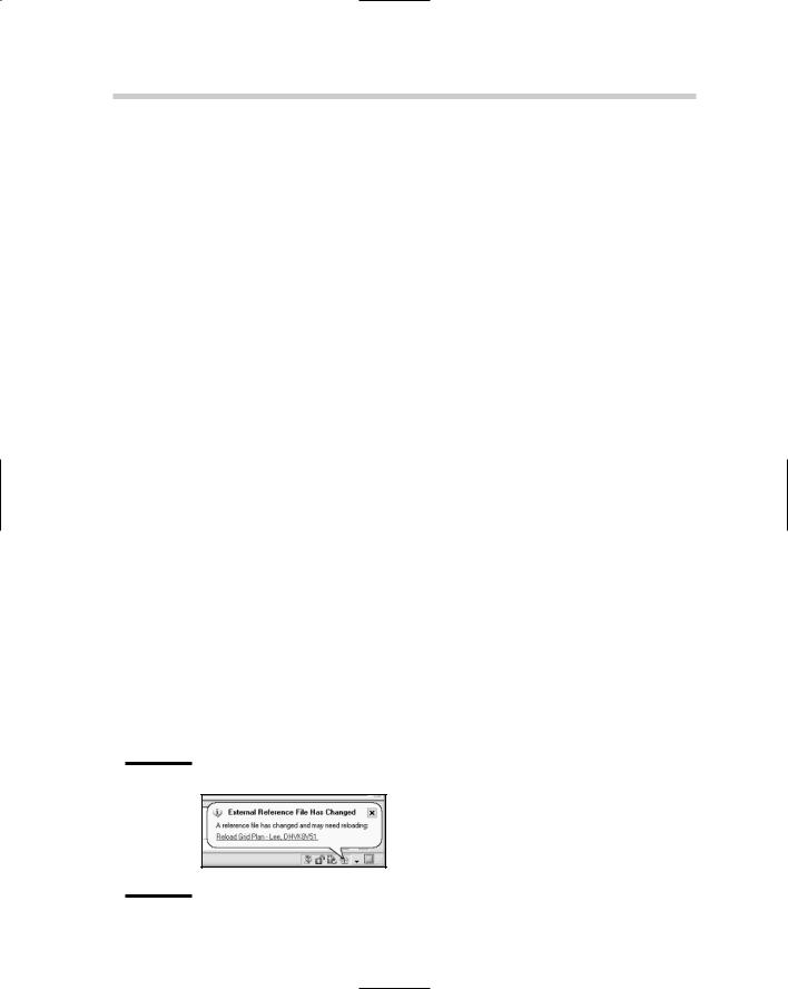
AutoCAD offers a notification system for various features. External references are part of this notification system. You can see when a drawing has an xref in it by the appearance of the Manage Xrefs icon in the status bar area. When a change occurs to one of the attached external references, the icon changes and a notification balloon is displayed (see Figure 3-3). Click the link in the notification balloon to reload the external references that have changed.
Figure 3-3:
Stay informed with the External Reference notification.
DWG References 387
The External Reference notification can be turned on and off with the XREFNOTIFY system variable (AutoCAD only). The default value is 2, which displays the balloon and the icon changes to reflect a change to one of the xrefs. Instead of completely disabling the notification, you may want to
use the TRAYSETTINGS command to control how long the notification is displayed.
Editing an xref
DWG references can be edited using many of the common editing commands that AutoCAD offers, but there are a few that are unique to xrefs. There will be times when you will want to make changes directly to the drawing file that are being referenced; in these cases, AutoCAD allows you to edit the xrefs in-place or open them in a drawing window. The commands that allow you to perform these editing operations are REFEDIT and XOPEN.
The commands REFEDIT and XOPEN are available only in AutoCAD and not AutoCAD LT.
Editing a reference in place
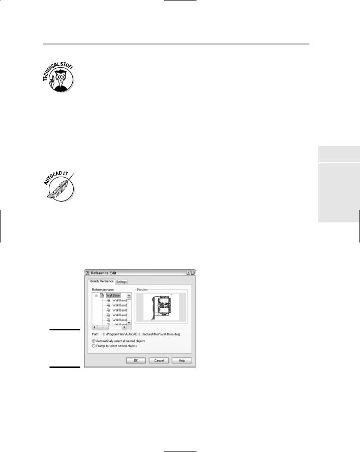
Initiating the REFEDIT command displays the Reference Edit dialog box (shown in Figure 3-4) and allows you to edit an xref or block in-place. AutoCAD opens the xref or block for modification right where it is inserted in the drawing. This can be great when you want to modify the xref or block based on surrounding objects in the drawing.
Figure 3-4:
Editing an xref or block in-place.
Book VI
Chapter 3
References External
388 DWG References
To start the REFEDIT command and display the Reference Edit dialog box, use one of the following methods:
Tools menu. Choose Tools Xref and Block In-Place Editing Edit Reference In-Place.
Refedit toolbar. Click the Edit Reference In-Place button on the Refedit toolbar.
Keyboard input. Type REFEDIT and press Enter.
Select an xref and right-click. From the shortcut menu, select Edit Xref In-Place.
Double-click. Double-click with the left mouse button over an xref.
Here’s how to edit a DWG reference:
1.Use any of the previously mentioned methods to initiate the REFEDIT command.
This command prompt is displayed at the command line:
Select reference:
2.At the command prompt, select the xref you want to edit.
The Reference Edit dialog box is displayed.
3.In the Reference Edit dialog box on the Identify Reference tab, select the Automatically Select All Nested Objects option.
This selects all the objects in the xref, even any attributes that it may contain.
4.Click the Settings tab to specify the additional settings you want to use during the in-place editing.
It is best to have the following options selected:
•Create unique layer, style, and block names
•Lock objects not in working set
This way, you can easily identify which objects you are working with.
5.Click OK.
The Reference Edit dialog box closes and the Refedit toolbar appears. This toolbar is useful for editing an xref in-place. All the objects that are not part of the xref are faded, which allows you to identify which objects are in the xref.
6.Modify the objects you want to change. You can add and remove objects from the xref by using the Add to Working Set and Remove from Working Set tools on the Refedit toolbar.
DWG References 389
7.Click Save Reference Edits on the Refedit toolbar to save the changes made.
A message box appears asking you to confirm the changes you are making to the xref.
8.Click OK on the message box to save the changes made.
The changes are committed back to the xref, and the in-place editing session is closed. The xref is automatically reloaded.
The degree to which the background objects are faded is controlled by the XFADECTL system variable. By default, the setting is 50.
Opening a reference
The XOPEN command opens an xref in its own drawing window, which enables you to use any editing commands without the limitations of the REFEDIT command. Once you save the changes to the file that is open for editing, the External Reference Notification is displayed, which allows you to reload the external reference by clicking the link.
Clipping an xref
Clipping an xref enables you to control how much of the xref is displayed. When working with large xrefs, loading the file can take a while. By clipping the xref, you can reduce the amount of time it takes to load it. The XCLIP command controls the clipping boundary of an xref. The XCLIP command has the following options:
ON. Enables the clipping for an xref.
OFF. Disables the clipping for an xref.
Clipdepth. Controls the distance of front and back clipping planes from the clipping boundary. The option has the options of Front, Back, Distance, and Remove.
Delete. Removes the clipping boundary for an xref.
Generate Polyline. Creates a Polyline object based on the clipping boundary.
New boundary. Adds a clipping boundary to the xref. You can create the clipping boundary by picking two points (rectangular), creating a closed polyline object by picking points (polyline), or selecting a closed polyline object.
Book VI
Chapter 3
References External
The XCLIP command is available only in AutoCAD and not AutoCAD LT. If you open a drawing that contains a clipped xref in AutoCAD LT, it displays clipped.
390 DWG References
To start the XCLIP command, use one of the following methods:
Modify menu. Choose Modify Clip Xref.
Reference toolbar. Click the Clip Xref button on the Reference toolbar.
Keyboard input. Type XCLIP and press Enter.
Command Alias. Type XC and press Enter.
Select an xref and right-click. From the shortcut menu, select Xref Clip.
Clipping a drawing reference (xref)
Here’s how to clip an xref based on a rectangular boundary:
1.Use any of the previously mentioned methods to initiate the XCLIP command.
This command prompt is displayed at the command line:
Select objects:
2.At the command prompt, select the xref that you want to clip and press Enter to end selecting objects.
The following command prompt appears at the command line:
Enter clipping option [ON/OFF/Clipdepth/Delete/generate Polyline/
New boundary] <New>:
3. Press Enter to accept the default option of creating a new boundary.
The following command appears at the command line:
Specify clipping boundary:
[Select polyline/Polygonal/Rectangular] <Rectangular>:
4.Press Enter to accept the default option of creating a rectangular clipping boundary.
The following command prompt appears at the command line.
Specify first corner:
5.Specify the first corner and then the opposite corner of the rectangular clipping boundary. The points should be outside the area of the xref you want left visible.
The command ends, and the xref is clipped based on the boundary you specified.
DWG References 391
The boundary that appears when you use the XCLIP command can be controlled by using the Modify menu, Object, External Reference, and clicking Frame. By default, the frame is hidden.
Even though the XCLIP command is intended to be used with xrefs, you can also use it to clip blocks.
Editing a clipped xref
You can modify the clipped boundary of an xref by running the XCLIP command again, or selecting the clip boundary and using grips to modify what is displayed. You can use the XCLIP command to replace the clipping boundary that is already assigned to the xref, remove the clip boundary, or turn the clip boundary on or off.
If you set the system variable XCLIPFRAME to a value of 0, you can’t use grips to modify the clip boundary of an xref. If you set XCLIPFRAME to a value of 1, you can modify the clip boundary of an xref.
Increasing the performance of xrefs
When you are working with a number of xrefs or working with large xrefs, there are a few things you can do to help increase performance. If you are no longer using some of the attached xrefs, the best thing to do is unload the xref through the External References palette. To unload an xref, select the xref and right-click. From the shortcut menu, select Unload. The link to the xref still exists, but the objects in the file are not loaded into memory. You can use the Reload option from the shortcut menu to load the xref back into the drawing if you need it later.
AutoCAD allows you to control how xrefs are loaded through a process called demand load. Demand loading helps improve the overall performance of working with xrefs by loading only the part of the drawing that is needed. Demand loading can be changed by selecting a new option from the Demand Load Xrefs drop-down list under the External References (Xrefs) section on the Open and Save tab of the Options dialog box. AutoCAD provides three options for demand loading:
Disabled. Demand loading is turned off and the entire drawing is loaded.
Enabled. Demand loading is turned off and only the part of the drawing that is required is loaded. This option locks the file so it can’t be edited by others by opening it or using the REFEDIT command.
New boundary. Demand loading is turned off and only the part of the drawing that is required is loaded. This option creates a copy of the drawing file, and the copy gets loaded into AutoCAD. The original file is not locked and allows others to edit the file by opening it or using the REFEDIT command. This is the default option that AutoCAD uses.
Book VI
Chapter 3
References External