Добавил:
Опубликованный материал нарушает ваши авторские права? Сообщите нам.
Вуз: Предмет: Файл:

AutoCAD & AutoCAD LT All-In-One Desk Reference For Dummies (2006)

.pdf
Скачиваний:
90
Добавлен:
17.08.2013
Размер:
17.7 Mб
Скачать

372 Going Dynamic

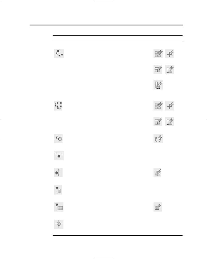
Table 2-1 (continued)


Parameter

Description

Actions


Modifies geometry in a block


along a polar path.


Polar


Array

Move


Scale

Stretch


Polar


Stretch


Modifies geometry in a block across a


horizontal and vertical distance.


XY


Array

Move


Scale

Stretch


Rotates geometry contained in the


block around a given point.


Rotation


Rotate


Aligns a block so it is perpendicular

No action required


or tangent to the geometry that it is


being inserted next to.


Alignment


Mirrors the entire block along a


reflection line.


Flip


Flip


Controls the display of geometry contained

No action required


within a block. Also can be used to have


one block that might display multiple differ-


Visibility

ent views or styles of similar geometry.


Creates a table with a list of values that


match up with a custom property.


Lookup


Lookup


Redefines the insertion point of a block.

No action required


Base Point

Going Dynamic 373

Adding parameters

You can add parameters to a block by using the Block Authoring Palettes or the BPARAMETER command. The following procedure uses the Block Authoring Palettes to add a point parameter to a block.

1.Open an existing block by using the Edit Block Definition dialog box, or create a new block using the Block Definition dialog box and make sure that the Open Block in Editor option is checked.

For information on the Edit Block Definition dialog box, see the section

“Editing a block definition” earlier in this chapter. For information on the Block Definition dialog box, see Chapter 1 in this minibook.

2.In the Block Editor, if the Block Authoring Palettes interface is not displayed, click the Authoring Palettes button on the Block Editor toolbar.

The Block Authoring Palettes interface should be displayed.

3.On the Block Authoring Palettes interface, click the Parameters tab and then click the Point Parameter tool.

The Parameters tab is displayed and the BPARAMETER command starts with the Point option.

4.At the command line or dynamic input tooltip, select a point in the drawing window for the parameter to reference, or select one of the available options by right-clicking and selecting the option from the shortcut menu.

Here is the command line prompt:

Command: _BParameter Point Specify parameter location or

[Name/Label/Chain/Description/Palette]:

5.In the Block Editor, select the location in the drawing window where you want the label to appear for the parameter.

This prompt is displayed at the command line:

Specify label location:

The label is a visual reference to the parameter. The label is used in the Block Editor, Properties palette, and to reference the property in a Field (AutoCAD only). The parameter will be displayed with a yellow box and an exclamation point in it (because no action has been associated with the parameter).

6.In the drawing window, select the parameter that was just placed and right-click. From the shortcut menu, select Properties.

The Properties palette appears with the parameter’s properties.

Book VI

Chapter 2

Blocks Dynamic

374 Going Dynamic

7.In the Properties palette, change the properties under the Property Labels, Geometry, and Misc areas to change the behavior of the parameter.

The Properties palette allows you to control the different types of properties associated with each parameter type. The properties vary based on each parameter.

8.In the Block Editor, click Save Block Definition on the toolbar.

A message box appears that allows you to save the changes to the block definition or cancel the current save.

9.In the message box, click Yes to save the changes made.

The message box closes. You can stay in the Block Editor to add actions, or click Close Block Editor to exit.

Adding actions

You add actions to a block by using the Block Authoring Palettes or the BACTIONTOOL command. The following steps use the Block Authoring Palettes to add a move action to a point parameter in a block:

1.Open an existing block using the Edit Block Definition dialog box, or create a new block using the Block Definition dialog box and make sure that the Open Block in Editor option is checked. If you create a new block, you need to first add a parameter to the block.

For information on the Edit Block Definition dialog box, see the section “Editing a block definition” earlier in this chapter. For information on the Block Definition dialog box, see Chapter 1 in this minibook.

2.In the Block Editor, if the Block Authoring Palettes interface is not displayed, click the Authoring Palettes button on the Block Editor toolbar.

The Block Authoring Palettes interface appears.

3.On the Block Authoring Palettes interface, click the Actions tab and then click the Move Action tool.

The Parameters tab is displayed and the BACTIONTOOL command starts with the Point option.

4.At the command line or dynamic input tooltip, select the parameter that you want to associate with the action.

The command line prompt is as follows:

Command: _BActionTool Move Select parameter:

Going Dynamic 375

5.In the Block Editor, select the parameter that you want to associate with the action.

The following prompt is displayed at the command line:

Specify selection set for action

Select objects:

6.Select the objects that you want to associate with the action, and press Enter when done selecting objects.

The following prompt appears at the command line:

Specify action location or [Multiplier/Offset]:

After you create the action, the yellow box with an exclamation point in it near the parameter disappears. This indicates that the parameter now has an action associated with it.

7.Specify a point in the Block Editor to place the action, or select one of the available options by right-clicking and selecting the option from the shortcut menu.

The point that you specify should be near the parameter so that you know which actions are associated with each parameter. The actual placement has no bearing on how the action works.

8.In the drawing window, select the action that was just placed and right-click. From the shortcut menu, select Properties.

The Properties palette appears, showing the action’s properties.

9.In the Properties palette, change the properties under the Property Labels, Geometry, and Misc areas to change the behavior of the parameter.

The Properties palette allows you to control the types of properties associated with each action type. The properties vary based on each action.

10.In the Block Editor, click Save Block Definition on the toolbar.

A message box appears that allows you to save the changes to the block definition or cancel the current save.

11.In the message box, click Yes to save the changes made.

The message box closes. You can stay in the Block Editor to add actions, or click Close Block Editor to exit the Block Editor.

Book VI

Chapter 2

Blocks Dynamic

Based on the parameter you selected, you may need to associate the action with a parameter point.

376 Going Dynamic

Using parameter sets

Using parameter sets is no different than placing a parameter and then an action. They simplify the process of having to place each individually by combining the two into a streamlined process. To use a parameter set, display the Block Authoring Palettes interface while in the Block Editor and click the Parameter Sets tab. When the Parameter Sets tab is active, click the parameter set you want to use and follow the prompts at the command line or the dynamic input tooltip.

Visibility states

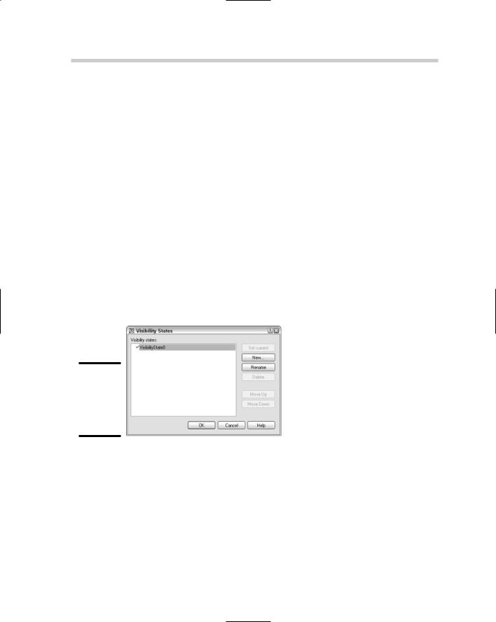
You can use visibility states to control the display of geometry within a block. This can be a great advantage when you are doing drawings and need to change out a block from one to another. For example, you may have a plumbing drawing that uses several types of valves. You can use one block to represent six types of valves. In releases prior to AutoCAD 2006, you had to erase the block and then find the other block to insert, which takes time. You can accomplish this task much more quickly by using dynamic blocks and visibility states. The Visibility States dialog box, shown in Figure 2-6, allows you to create, rename, delete, set current, or change the order of a visibility state for the block.

Figure 2-6:

Managing and creating visibility states in one place.

Follow these steps to place a visibility parameter in a block:

1.Open an existing block using the Edit Block Definition dialog box, or create a new block using the Block Definition dialog box and make sure the Open Block in Editor option is checked.

For information on the Edit Block Definition dialog box, see the section “Editing a block definition” earlier in this chapter. For information on the Block Definition dialog box, see Chapter 1 in this minibook.

Going Dynamic 377

2.In the Block Editor, if the Block Authoring Palettes interface is not displayed, click the Authoring Palettes button on the Block Editor toolbar.

The Block Authoring Palettes interface appears.

3.On the Block Authoring Palettes interface, click the Parameters tab and then click the Visibility Parameter tool.

The Parameters tab is displayed, and the BPARAMETER command starts with the Visibility option.

4.At the command line or dynamic input tooltip, select a point in the drawing window for the visibility grip to be displayed, or select one of

the available options by right-clicking and selecting the option from the shortcut menu.

Following is the command line prompt:

Command: _BParameter Visibility

Specify parameter location or [Name/Label /Description/Palette]:

5.In the drawing window, select the parameter that was just placed and right-click. From the shortcut menu, choose Properties.

The Properties palette appears, showing the parameter’s properties.

6.In the Properties palette, change the properties under the Property Labels, Geometry, and Misc areas to change the behavior of the parameter.

Follow these steps to define a new visibility state and associate geometry in the block to the visibility state for a block:

1.On the Block Editor toolbar, click the Manage Visibility States button.

The Visibility States dialog box appears.

2.In the Visibility States dialog box, click New.

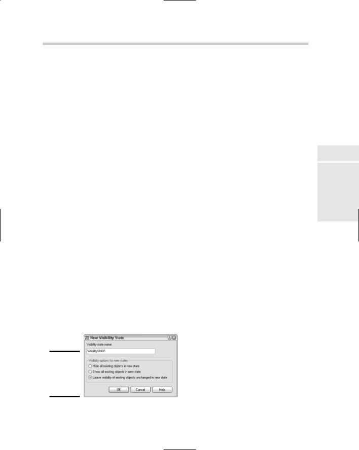
The New Visibility State dialog box appears (see Figure 2-7).

Figure 2-7:

Defining a new visibility state.

Book VI

Chapter 2

Blocks Dynamic

378 Using Dynamic Blocks

3.Enter a name in the Visibility State Name text box.

You use the name to select and manage the visibility state when the block has been inserted into the drawing.

4.Specify one of the three options under the Visibility Options for New States.

These options control the display of the geometry in the drawing. You can hide or show all the objects in the block, or leave the objects as they appear based on the current visibility state.

5.Click OK.

The New Visibility State dialog box is closed, and you are returned to the Visibility States dialog box. The new visibility state is listed in the list box.

6.In the Visibility State dialog box, click OK.

The Visibility State dialog box is closed, and you are returned to the Block Editor.

7.In the Block Editor, select the visibility state you want to modify by choosing it from the Visibility State drop-down list on the toolbar.

The visibility state is set current.

8.Click either the Make Visible or Make Invisible.

If you click Make Visible, all the geometry currently marked as invisible is displayed in a light gray color so you can select them and make them visible again. If you click Make Invisible, only the visible geometry is displayed, allowing you to select which should not be displayed.

9.Click the visibility state from the Visibility State drop-down list that you want to use as the default state.

The selected visibility state will be the one that is displayed when the block is initially inserted into the drawing.

10.On the Block Editor toolbar, click the Save Block Definition button.

A message box appears that allows you to save the changes to the block definition or cancel the current save.

11.Click Yes to save the changes made.

The message box closes. You can stay in the Block Editor to add actions or click Close Block Editor to exit the Block Editor.

Using Dynamic Blocks

Dynamic blocks can be used and modified similar to how you use a legacy block, including the methods you use for inserting blocks, editing attributes,

Using Dynamic Blocks 379

and manipulating properties through the Properties palette. Some differences exist between the two, however, which are covered in the following sections.

Inserting a dynamic block

Dynamic blocks are inserted into the drawing just like you would insert a legacy block. You can use the Insert dialog box by starting the INSERT command and dragging and dropping blocks from the DesignCenter or Tool Palettes window. Chapter 4 of this minibook discusses DesignCenter and the Tool Palettes window. If you use the Tool Palettes window to insert a dynamic block, you can specify the value for each of its custom properties before the block is inserted into the drawing.

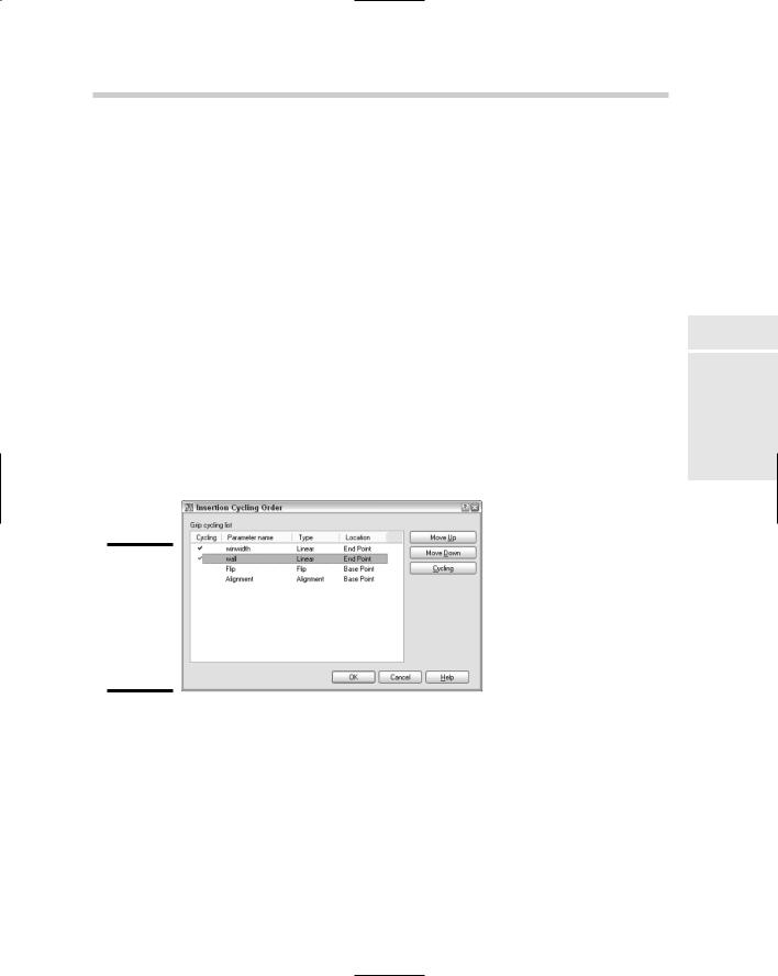
While the block is being dragged on-screen, you can toggle through the points at which parameters are referencing in the dynamic block. These points are called the insertion cycling order. You can specify the insertion cycling order while you are in the Block Editor by using the Insertion Cycling Order dialog box (see Figure 2-8), which is displayed by choosing the BCYCLEORDER command. Pressing the Ctrl key toggles through the various insertion cycling points in the block while you drag the block on-screen.

Figure 2-8:

Defining insertion cycling for a block can make inserting it easier.

Modifying a dynamic block

The key benefit to dynamic blocks is that they can be manipulated without first being exploded. After you finish adding the parameters to a block and associating actions to each parameter that needs one, you can modify the block without exploding it. This allows you to take advantage of attributes in your drawing, which would not be possible if you exploded the block.

Book VI

Chapter 2

Blocks Dynamic

380 Dynamic Blocks in Older Releases

Using a dynamic block’s custom grips

To modify a dynamic block, you can select the block to enable its grips and manipulate the geometry assigned to the parameter and action. You can also use the Properties palette to manipulate custom properties of a dynamic block under the Custom area. Select the custom property in the Properties palette and change its value. Some custom properties reference points, rotation angles, or a list of values.

Resetting a dynamic block

You may want to reset a dynamic block to its initial state. You can reinsert the block, but that requires unnecessary work. AutoCAD allows you to reset a dynamic block to its initial state by using the Reset Block option from the shortcut menu that appears when you select the block and right-click. Doing so resets only the custom properties of the block and none of the attribute values.

The RESETBLOCK command allows you to reset multiple block references at a single time.

Dynamic Blocks in Older Releases

When an AutoCAD 2007 file is saved to an older release (with the exception of AutoCAD 2006), the dynamic blocks appear as if they were static blocks. Dynamic blocks when listed in a release prior to AutoCAD 2006 show as anonymous blocks, which is a name that is assigned by AutoCAD and not the name that the block is given when it is created. The custom properties do not work in an older release because the release doesn’t understand the information. If the block is left unaltered in an older release after it is saved to a previous version, the dynamic properties of the block will work again when the drawing is reopened in AutoCAD 2006 or later. If the dynamic block contains Fields in its attributes, AutoCAD displays the Field values with their last updated value.

Because dynamic blocks are relatively new, older applications that are used to extend AutoCAD and work with blocks may not work correctly with dynamic blocks. You must test each application that manipulates blocks with dynamic blocks, and if they don’t work correctly, you need to contact the vendor of the application to see if an updated version is available.

Chapter 3: External References

In This Chapter

Blocks versus External references

DWG references

DWF underlays

Raster images

Controlling object display with draw order

Object linking and embedding (OLE)

Managing external references outside of AutoCAD

The first two chapters of this minibook explain how to create blocks and dynamic blocks. Blocks form the cornerstone of reusable content in drawings. In this chapter, you read about external references and how you can use them to improve communication and keep file size down. External references are used to link DWG, DWF, and raster image (AutoCAD only) files into a drawing. By linking these files into the drawing, it allows you to have

the most up-to-date geometry or image displayed. Some types of external references allow you to snap directly to the geometry that they reference.

Blocks versus External References

Blocks are groups of objects that have a specific name. The block is stored in the drawing file and when a change is required, it needs to be redefined in the drawing. This can be a problem if the block is contained in a number of different drawings. External references might be a group of objects but can also be an image file. External references don’t have all their geometry stored in the drawing file; external references maintain in the drawing only a reference to the filename, its inserted location, and its scale and angle of rotation. When you open a drawing that references the external reference, the external reference file is reloaded. This makes external references ideal for buildings that can span multiple drawings. The floor plan could be in an external reference, which allows others to reference the floor plan without inserting all the objects into each drawing.