Добавил:
Опубликованный материал нарушает ваши авторские права? Сообщите нам.
Вуз: Предмет: Файл:

AutoCAD & AutoCAD LT All-In-One Desk Reference For Dummies (2006)

.pdf
Скачиваний:
90
Добавлен:
17.08.2013
Размер:
17.7 Mб
Скачать

362 Enhancing Blocks with Attributes

on whether you checked the Specify On-Screen options for the insertion point. If you need to specify an insertion point for the attribute definition, the following prompt will be displayed:

Specify start point:

10.Start the BLOCK command and create the block like you normally would — just don’t forget to add the attribute.

When you insert a block with attributes or edit the attribute values, you are prompted to edit the attribute values in a specific order. This order is determined by how the attributes are added to the selection set when the block is created. Select each attribute in the order you want to see it displayed when you insert or edit the block.

Inserting a block with attributes

You insert a block with attributes the same way as you insert a block without attributes, except that after the block has been inserted into the drawing, you are prompted to change the values for the attributes that are contained in the block with the Edit Attributes dialog box (see Figure 1-5) or at the command line. You are not prompted for attributes that are flagged as Constant or Preset.

Figure 1-5:

Editing attribute values after a block is inserted.

The system variables ATTDIA and ATTREQ affect how you are prompted for attribute values when you insert a block. ATTDIA toggles the display of the Edit Attributes dialog box or the use of the command line for changing attribute values when a block with attributes is inserted into a drawing. ATTREQ controls whether prompts for changing attributes even appear when a block with attributes is inserted into a drawing.

Enhancing Blocks with Attributes 363

Changing an attribute’s value in a block

You can change attribute values that are stored in a block by using the Properties palette, ATTEDIT (Edit Attributes), EATTEDT (Enhanced Attribute Editor) — AutoCAD only, or DDEDIT (Edit Text) commands. The easiest

way is to double-click the block that has attributes you want to edit, which launches the default attribute editor. Make the change to the attributes in the dialog box that is displayed.

Managing attributes in blocks

When you redefine blocks with attributes, you need to be aware of a few additional commands. Attributes are part of a block, but they are not added to a block reference until you insert the block reference into a drawing. If you redefine a block and add attributes to a block, use the ATTSYNC (Attribute Synchronize) command. Using this command ensures that all the existing blocks in the drawing are updated. The BATTMAN (Block Attribute Manager) command is used to modify the properties of the attributes on a block. You can use this command to change the order in which the attributes appear when edited.

Extracting attribute data from blocks

You can extract attributes from a drawing by using the ATTEXT (Attribute Extraction) command, which you can find in both AutoCAD and AutoCAD LT, or the EATTEXT (Enhanced Attribute Extraction), which is available only in AutoCAD and not AutoCAD LT. For information on extracting attributes out of your drawing, see the online Help topic “Extract Data from Block Attributes,” which you can access from the Contents tab of the online Help system. Choose User’s Guide Create and Modify Objects Create Use Blocks (Symbols) Attach Data to Blocks (Block Attributes).

Book VI

Chapter 1

with Playing

Blocks

364 Book VI: Advanced Drafting

Chapter 2: Dynamic Blocks

In This Chapter

Understanding what makes a block dynamic

Adding parameters and actions to a block

Working with visibility states

Understanding what happens to dynamic blocks in older releases

In Chapter 1 of this minibook, we discuss how to create and manage blocks with or without attributes. The types of blocks that you created

using the BLOCK command and any blocks that were created prior to AutoCAD 2006 are known as a static block or a legacy block (1.0 version of blocks). AutoCAD 2006 introduced a new type of block called a dynamic block (2.0 version of blocks). Static blocks can primarily be altered through placement, rotation, overall scaling, and editing attributes. Dynamic blocks take static blocks and enhance them by adding a new level of editing. Dynamic blocks can allow you to stretch geometry in the block in one direction and confine the distance by set increments. This chapter focuses on how to add dynamic behavior to a block.

Dynamic blocks are supported in AutoCAD LT 2006, but they can’t be created. AutoCAD LT 2007 supports the creation of dynamic blocks, with some limitations. One of the main limitations is the ability to use Fields in attributes. (Fields are not supported by AutoCAD LT.)

What Makes a Block Dynamic?

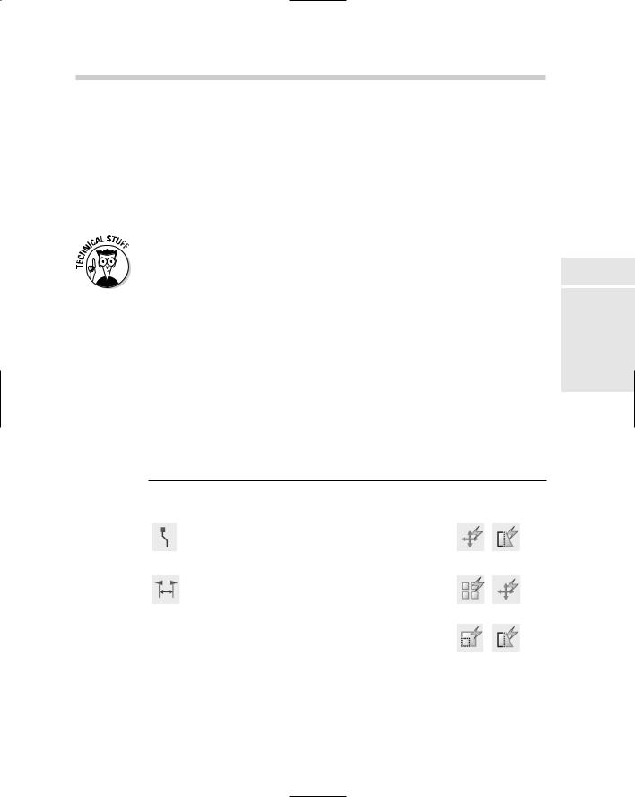
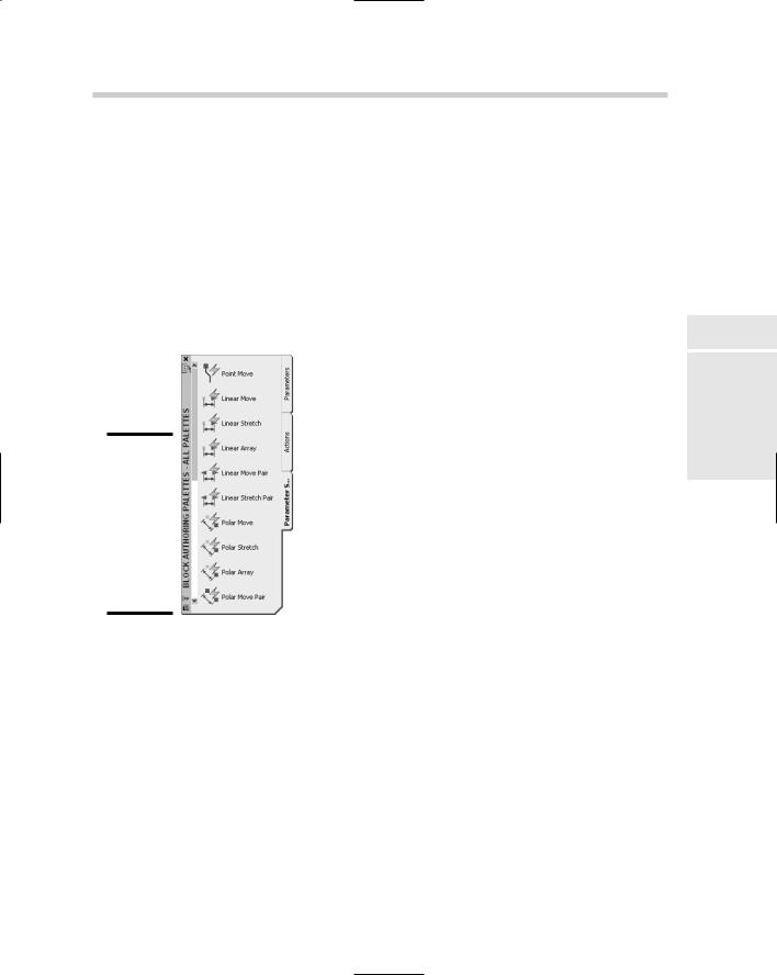
Dynamic blocks are static blocks with some new tricks — maybe you can teach an old block new tricks. Dynamic blocks are created in the Block Editor. They contain custom properties by adding parameters and actions. Parameters and actions bring blocks to life by allowing you to rotate, move, or modify objects within each instance of a block. If you want to move objects within a static block, you simply explode the block and then reblock it with a different name; otherwise, reblocking the block with the same name changes all the instances of that block in the drawing. Dynamic blocks allow you to assign the following actions to objects within a block:

366 Block Editor Environment

Move

Rotate

Scale

Flip (or Mirror)

Stretch

Array

Polar Stretch

Lookups

After parameters and actions have been assigned to a block, the block doesn’t look any different until you select it when no command is running. Based on the type of parameters added to the block, you will see different types of grips appear. Some of these grips appear in the form of circles, arrows, and triangles (see Figure 2-1).

Figure 2-1:

Dynamic blocks can display different types of grips.

Block Editor Environment

The Block Editor, shown in Figure 2-2, was mentioned briefly in Chapter 1 of this minibook because it can be opened when creating a block with the Block Definition dialog box. The Block Editor is a special instance of the drawing window that allows you to work with a block definition in the same way that you would with a drawing file and is used to extend the behavior of a block through the use of parameters and actions. Unlike the main window, the Block Editor doesn’t allow you to use some commands, such as BLOCK, REFEDIT (AutoCAD only), and PLOT, and it doesn’t contain layout tabs because blocks cannot contain layouts.

After you open the block definition, you can add or remove geometry, add or remove parameters and actions, and work with attributes. If you are using AutoCAD and not AutoCAD LT, you can capture block and custom properties by using Fields that can be used in attributes.

Block Editor Environment 367

Figure 2-2:

The Block Editor is used to modify block definitions.

Components of the Block Editor

Even though the Block Editor is similar to a drawing window, it still uses some specialized interfaces. One of these interfaces is a toolbar along the top of the drawing window (see Figure 2-3). This toolbar contains tools that you can use to enhance a legacy block or modify a dynamic block. Here is a list of what you can accomplish by using the Block Editor toolbar:

Edit or Create Block Definition. Displays the Edit Block Definition dialog box and allows you to open a different block definition from inside the Block Editor.

Save Block Definition. Saves the changes made to the block definition.

Save Block As. Displays the Save Block As dialog box and allows you to save the block definition as a new block.

Block Definition Name. Displays the open block definition’s name.

Authoring Palettes. Displays or hides the Block Authoring Palettes window.

Parameter. Starts the BPARAMTER command and allows you to add a parameter without using the Block Authoring palettes.

Action. Starts the BACTION command and allows you to add an action without using the Block Authoring palettes.

Define Attribute. Starts the ATTDEF command and displays the Attribute Definition dialog box, allowing you to add an attribute definition to the block definition.

Update Parameter and Action Text Size. Starts the REGEN command to update the display of text, arrowheads, grips, and a few other display

Book VI

Chapter 2

Blocks Dynamic

368 Block Editor Environment

elements in the Block Editor. (These elements are based on the current zoom factor of the drawing window.)

Learn About Dynamic Blocks. Starts the New Features Workshop.

Close Block Editor. Closes the Block Editor and prompts you to save any changes that were made.

Visibility Mode. Controls the current visibility of objects in the Block Editor that have been assigned to a Visibility State.

Make Visible. Starts the BVHIDE command and allows you to associate objects that are currently invisible in the current visibility state.

Make Invisible. Starts the BVHIDE command and allows you to disassociate objects from the current visibility state.

Manage Visibility States. Displays the Visibility States dialog box so you can create, edit, or delete visibility states from the block.

Block Visibility State List. Specifies which visibility state is current.

Figure 2-3:

The Block Editor toolbar allows you to access some of the specialized functionality found in the Block Editor.

Save Block Definition

Block Definition Name

Parameter

Define Attribute

Learn About Dynamic Blocks

Visibility Mode

Make Invisible

Block Visibility State List

Manage Visibility States

Make Visible

Close Block Editor

Update Parameter and Action Text Size

Action

Authoring Palettes

Save Block As

Edit or Create Block Definition

Block Editor Environment 369

You can use the Block Authoring Palettes window (see Figure 2-4) to place parameters and actions in a block. By using the parameters, you can also define custom properties for the block. After a parameter has been added to the block, an action must be associated with that parameter. The action is used to define how the geometry that is associated with the parameter should be moved or changed in the drawing. The Block Authoring Palettes window has three tabs on it, one for the available parameters and one for the available actions. The final tab is one that contains both parameters and actions in what are called parameter sets. If you are new to creating dynamic

blocks, the parameter sets allow you to get up the learning curve much faster by combining many of the common parameter and action combinations into easy-to-use tools.

Figure 2-4:

The Block Authoring Palettes window contains parameters and actions for dynamic blocks.

Editing a block definition

To start the Block Editor, you use the BEDIT command. The BEDIT command displays the Edit Block Definition dialog box (see Figure 2-5). From the Edit Block Definition dialog box, you select a block from the list to edit or enter a name in the text box to create a new block. The Edit Block Definition dialog box displays a preview of the block that is selected from the list and its associated description. If the preview displays a small lightning bolt in the lowerright corner, the selected block is a dynamic block. This indicator is displayed in many of the different interfaces and dialog boxes where block previews are displayed.

Book VI

Chapter 2

Blocks Dynamic

370 Block Editor Environment
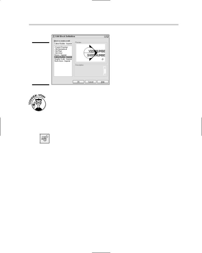
Figure 2-5:

Use the Edit Block Definition dialog box to open

a block definition for editing.

When set to 0, the system variable BLOCKEDITLOCK allows you to edit blocks by using the BEDIT command. When set to a value of 1, it doesn’t allow the BEDIT command to be started, and in turn, restricts the modifying of dynamic properties of a block.

To start the BEDIT command and display the Edit Block Definition dialog box, use one of the following methods:

Tools menu. Choose Tools Block Editor.

Standard toolbar. Click the Block Editor tool on the Standard toolbar.

Keyboard input. Type BEDIT and press Enter.

Command alias. Type BE and press Enter.

Shortcut menu. Select a block and right-click. From the shortcut menu, select Block Editor. This option automatically opens the selected block’s block definition in the Block Editor.

The following procedure uses the Tools menu to start the command and modifies a block.

1.Start the BEDIT command by using one of the methods described in the preceding list.

The Edit Block Definition dialog box appears.

2.In the Edit Block Definition dialog box, select a block from the list and click OK.

The selected block is opened in the Block Editor. If a message box is displayed about seeing how dynamic blocks are created, click No. If you want to suppress the message box so it is not shown in the future, check the Do Not Display This Alert Again option.

3.Make the necessary changes to the block.

Going Dynamic 371

4.On the Block Editor toolbar that is displayed along the top of the Block Editor, click Close Block Editor.

A message box asks you to save your changes.

5.Click Yes on the message box to save the changes.

Clicking Yes closes the Block Editor and saves the changes made to the block definition. If you click No, the Block Editor closes and the changes are discarded, and if you click Cancel, you remain in the Block Editor.

If you add or remove attributes from the block definition, the changes are not reflected in the block references that currently exist in the drawing until you erase and reinsert the blocks. If you are using AutoCAD and not AutoCAD LT, you can use the ATTSYNC command to update the attributes on the block references.

Going Dynamic

Once you have a block open in the Block Editor, you can add parameters and actions to your block. Most parameters require an action in order for them to be used, but there are a few that require no actions. AutoCAD offers ten parameters for you to place in the drawing, three that do not require any associated actions.

Table 2-1 lists the available parameters and the actions that can be associated with them.


Table 2-1

Parameters and Actions


Parameter

Description

Actions


Defines a point in the block so you


can move or change geometry


associated with the point.


Point

Move

Stretch


Modifies geometry in a block along


a linear path.


Linear


Array

Move


Scale

Stretch


Book VI

Chapter 2

Blocks Dynamic

(continued)