2.Use any of the four methods just listed to initiate the BLOCK command.
The Block Definition dialog box appears (refer to Figure 1-1).
3.In the Name combo box, enter a meaningful name.
The name entered must be unique from others that already exist in the drawing, or you end up redefining the existing block. The name entered must be 255 characters or less.
4.Under the Base Point area, either click the Pick Point button and select a point in the drawing, or enter the coordinate value for the base point in the X, Y, and Z text boxes.
The point that you specify will be used as the base point of the block or its insertion point. Usually this point is on the geometry that is being selected to make up the block.
5.If you clicked the Pick Point button under the Base Point area, you are returned to the drawing window. Specify a point in the drawing to use as the base point for the block.
After you select the base point for the block in the drawing window, you return to the Block Definition dialog box.
6.Under the Objects area, click the Select Objects button.
You are returned to the drawing window where you can select the objects that you want to add to the block.
7.In the drawing window, select the objects you want to add to the block. Press Enter to complete selecting objects and return to the Block Definition dialog box.
The objects you select can be text, lines, circles, and even other blocks. Any object you can select can be added to the block. You can use the QuickSelect button to the right of the Select Objects button to filter objects by specific property values. Quick Select was covered under Chapter 5 of Book VI.
8.In the Block Definition dialog box under the Objects area, click one of the selected object modes.
The different object modes affect what happens to the selected objects after the block is created.
•Retain. The selected objects are left as in the drawing.
•Convert to block. The selected objects are removed from the drawing, but the new block is inserted at the same location of the original objects.
•Delete. The selected objects are removed from the drawing.
Inserting Blocks
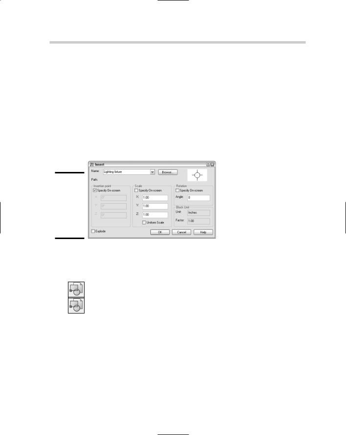
AutoCAD stores blocks in what is called the block definition table. The block definition table is used to hold information and settings about the block. In order to get the block to be displayed in the drawing, you need to insert a reference to the block definition from the table. An inserted block in the drawing is known as a block reference because it refers back to its definition in the table. To insert a block into the current drawing file, you use the INSERT command, which opens the Insert dialog box (see Figure 1-2). The INSERT command can insert a block from within the current drawing or an entire drawing file as a block. It just depends on where the information you want to insert into the drawing is located.
Figure 1-2:
The Insert dialog box is used to create a reference to a block definition.
To start the INSERT command and display the Insert dialog box, follow one of the following methods:
Insert menu. Choose Insert Block.
Insert toolbar. Click the Insert Block tool on the Insert toolbar.
Draw toolbar. Click the Insert Block tool from the Insert flyout on the Draw toolbar.
Keyboard input. Type INSERT and press Enter.
Command alias. Type I and press Enter.
The following procedure starts the INSERT command and explains how to insert a block into a drawing.
1.Use any of the previously listed methods to initiate the INSERT command.
The Insert dialog box appears (refer to Figure 1-2).
356 Managing Blocks
INSUNITS value, close the Insert dialog box and type INSUNITS at the command line or the dynamic input tooltip. Then enter the corresponding integer for the insertion units you want. For more information, look up the topic “INSUNITS” in the AutoCAD online Help.
8.At the bottom of the Insert dialog box, check or uncheck if you want the block to be exploded after it is inserted into the drawing.
If the Allow Exploding option was unchecked in the Block Definition dialog box when the block was created, the Explode option is disabled.
9.Click OK.
The Insert dialog box closes, and you are returned to the drawing window. The INSERT command may still be running based on whether you checked any of the Specify On-Screen options for the insertion point, scale, or rotation. Specify the prompts as required. Here are the three possible prompts:
Specify insertion point or [Basepoint/Scale/Rotate]:
Specify scale factor <1>:
Specify rotation angle <0>:
You can create custom toolbars or pull-down menus to help insert blocks. If you do create your own custom toolbars and menus, you need to use
the –INSERT command instead of the INSERT command for the menu macro. You must run the –INSERT command from the command line or dynamic input tooltip.
Managing Blocks
Blocks are a powerful feature of AutoCAD and no doubt you will be using them as often as you can. AutoCAD offers several tools and commands for managing blocks. Some of the ways to manage blocks in a drawing are as follows:
Rename a block definition
Redefine a block definition
Purge a block definition
Export a block to its own drawing file
Renaming a block definition
You can rename blocks by using the RENAME command. Follow these steps to rename a block:
1.At the command line or the dynamic input tooltip, type RENAME and press Enter.
2.At the command line or the dynamic input tooltip, type PURGE and press Enter.
3.In the Purge dialog box, double-click the All Items node if it is not already expanded, and then expand the Blocks node.
The block definitions that can be purged appear.
4.Select the block and click Purge.
By default the Confirm Purge dialog box is displayed.
5.On the Confirm Purge dialog box, click Yes.
The block definition is removed from below the Blocks node and from the drawing.
6.Click Close to exit the Purge dialog box.
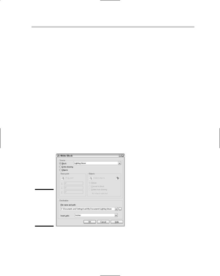
Exporting a block definition
Blocks that are created using the BLOCK command are defined in the current drawing only, but many times you will want to be able to access the block from other drawings. The Write Block dialog box, shown in Figure 1-3, is used to export a block out of the current drawing and make a new drawing file based on a selected block. The Write Block dialog box is displayed with the WBLOCK command.
Figure 1-3:
The Write Block dialog box is used to export a block definition
Follow these steps to export a block definition to a new drawing file:
1.At the command line or the dynamic input tooltip, type WBLOCK and press Enter.
360 Enhancing Blocks with Attributes
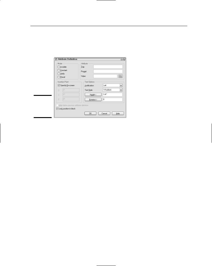
actual attribute of the block reference should be like. To create an attribute definition, you choose the ATTDEF command to display the Attribute Definition dialog box (see Figure 1-4).
Figure 1-4:
Creating an attribute definition.
To start the ATTDEF command and display the Attribute Definition dialog box, follow one of the following methods:
Draw menu. Choose Draw Block Define Attributes.
Keyboard input. Type ATTDEF and press Enter.
Command alias. Type ATT and press Enter.
The following procedure starts the ATTDEF command and explains how to create an attribute definition and then add it to a block.
1.Add the geometry to your drawing that you want to combine into a block.
2.Use any of the methods previously listed to initiate the ATTDEF command.
The Attribute Definition dialog box appears (refer to Figure 1-4).
3.In the Attribute Definition dialog box, select the options under the Mode area that you want to use for the attribute definition.
Attributes can have four different modes:
•Invisible. When this option is checked, the attribute is invisible. By default, the attribute is invisible, but the system variable ATTMODE set to a value of 2 displays all invisible attributes in the drawing.