342 Getting the Right Look with Materials
you to create and edit materials based on a variety of properties such as transparency, shininess, a bump map, or simply a color. After the material is created, it needs to get in the scene somehow. Here are the three ways you can associate a material in a scene:
Materials by Layer: Materials can be assigned to objects globally throughout a scene by assigning the material to a layer. Use the MATERIALATTACH command to assign a material to a layer in the scene.
Materials by Object: Materials can be assigned to an individual object in the scene by using the MATERIALASSIGN command and selecting the object(s) you want to assign the material to.
Materials by Face: Materials can be assigned to an individual face of a 3D solid by holding down the Ctrl while using the MATERIALASSIGN command, or using the SOLIDEDIT command and assigning a material using the Face option.
The MATERIALS, MATERIALATTACH, and MATERIALASSIGN commands are new in AutoCAD 2007.
Figure 7-8:
The Materials palette.
Rendering the Final Scene 343
Setting Up a Backdrop
Backgrounds allow you to fill what looks like empty space beyond the 3D model in your scene. The background of the current view can be defined as a solid color, a gradient that consists of two or three colors, or an image file. To set the background of the current view, use the Background Override property of the view in the View Manager.
The BACKGROUND command has been removed from AutoCAD 2007. You now use the VIEW command and the View Manager to assign a background to a named view.
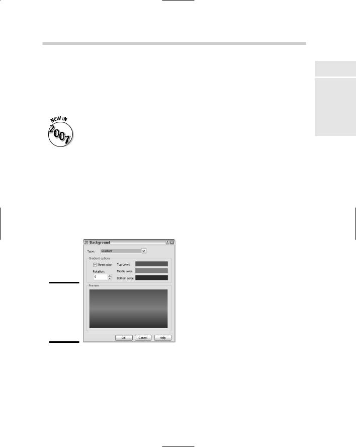
In the View Manager, select the view that you want to change the background for from the View list. You can only select views that are under the Model Views and Layout Views branches. After you have selected the view, under the General section, select the Background Override property. Then select the drop-down list next to Background Override and choose the option you want to use to open the Background dialog box (see Figure 7-9). Specify the options as desired and click OK to the exit Background dialog box. To set the view current and use the new background, select the view from the View list and click Set Current. When you exit the dialog box, the background is displayed along with the view that was selected.
Figure 7-9:
The Background dialog box with Gradient selected.
Rendering the Final Scene
Book V
Chapter 7
Cameras,AutoCAD! |
Rendering:Lights, |
After you have created your 3D model, put lights in the scene, created and applied materials, and put a background in the current view, you are ready for the final step of putting together your image. During the rendering
344 Rendering the Final Scene
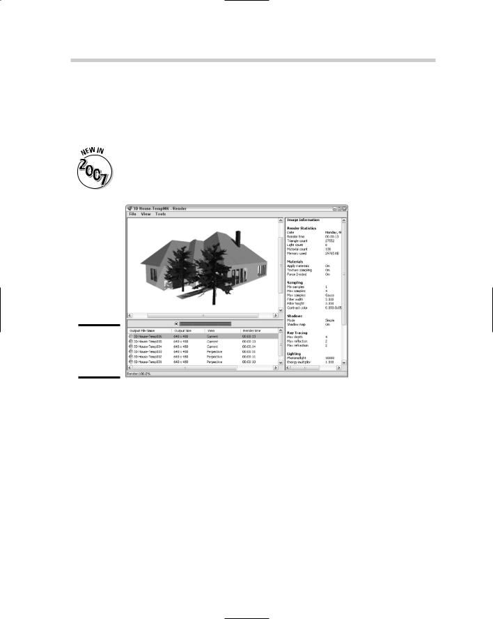
process, AutoCAD gathers all the materials and applies them to the objects and faces of your 3D model and calculates both light and shadows for the scene. Rendering takes place by default in the Render Window dialog box (see Figure 7-10). To start the RENDER command, you can choose View Render Render, or select the Render button in the Render control panel of the Dashboard.
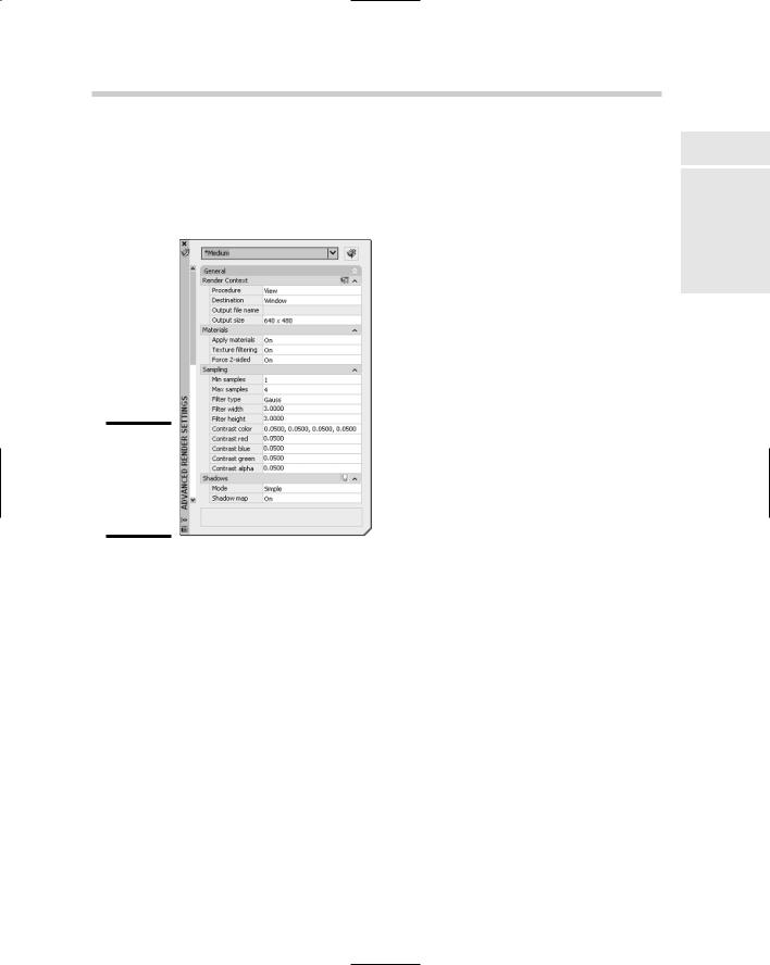
The RENDERCROP and RENDERWIN commands are new in AutoCAD 2007, and the RPREF and RENDER commands have been updated. The RPREF command now displays the Advanced Render Settings palette.
Figure 7-10:
The Render Window dialog box.
Instead of rendering the entire scene to the Render Window, you can use the RENDERCROP command and specify the part of the current view that you want to render. This is a great way to test your lighting and shadows in a specific part of the scene without having to render everything in the scene. The rendering happens directly in the current viewport. AutoCAD allows you to select from five different render presets to help speed up the process. A render preset can be selected from the drop-down list in the Render control panel on the Dashboard. Render presets range from very quick renderings using the draft setting, which makes your objects appear very grainy, to a presentation-quality preset, which can significantly increase rendering times.
If the render presets don’t offer the exact look you want, you can choose Manage Render Presets from the render presets drop-down list. Then you can create a copy of one of the render presets and customize it the way you
Chapter 1: Playing with Blocks
In This Chapter
Creating blocks
Inserting blocks
Managing blocks
Using attributes to store information
This book of the AutoCAD & AutoCAD LT All-in-One Desk Reference
For Dummies takes a look at creating and managing reusable content. Reusable content is content that needs to be created only once and then can be used in many different drawings. The ability of CAD to reuse content was a huge advantage for those drafters who ventured into the world of CAD early on. If you have ever had the pleasure of drafting on a board, you may have used plastic templates for things like circles, furniture in a house plan, and mechanical fasteners. These plastic templates allowed you to draw the same objects over and over again without drawing them completely from scratch each time.
Working with Reusable Content
AutoCAD allows you to create geometry templates called blocks. A block is an object that is made up of many different objects and given a name to reference when you want to place the block in a drawing. Blocks are great for providing a consistent look to your drawings. You may have already used a block in your drawings for a border that contains project name, date, and other information that relates to that particular drawing. Blocks can be defined with static or dynamic geometry. You also can associate different information with each instance of the block inserted into the drawing through the use of attributes. Attributes are often used to store costing, descriptions, room numbers, and other information that a user would like to extract out of a drawing based on each instance of a block. The extracted attribute information can be imported into an external application, such as Microsoft Excel, or even placed on a drawing in a table object.

Blocks are not the only form of reusable content in AutoCAD. AutoCAD can reference entire drawings and files into a drawing, called external referencing. When a drawing file is referenced into another drawing, it is referred to as an xref. Xrefs allow you to share drawings with others who may need to ensure that their drawings match up with yours. For example, you can share a floor plan with the building systems contractor and the landscaper at one time. If the floor plan is used as an xref, the next time the drawing is opened by the contractors, the updates are displayed (of course, they would need the updated drawing file). AutoCAD is also capable of referencing file raster images and DWF files.
Drawings often display schedules. Sometimes drafters create this information in a word processor or spreadsheet program. AutoCAD allows you to copy and paste content from Windows-based applications through the use of the Windows Clipboard, but doing so causes the information to become static. AutoCAD can keep some of this information dynamic through the use of Object Linking and Embedding (OLE). Being able to reuse content has advantages, but being able to access that content quickly makes it even more valuable. AutoCAD provides two interfaces that allow you to organize and access content quickly; these interfaces are called the DesignCenter and Tool Palettes window. For more information on DesignCenter and the Tool Palettes window, see Chapter 4 of Book VI.
Creating Blocks
Creating a block isn’t all that difficult once you have the objects created that you want to combine into a block. Blocks contain geometry and text that you create in AutoCAD, such as rectangles, circles, arcs, and lines. All you have to do, for example, is draw a table and some chairs. When you create the block, it looks just like the original objects you used to create it.
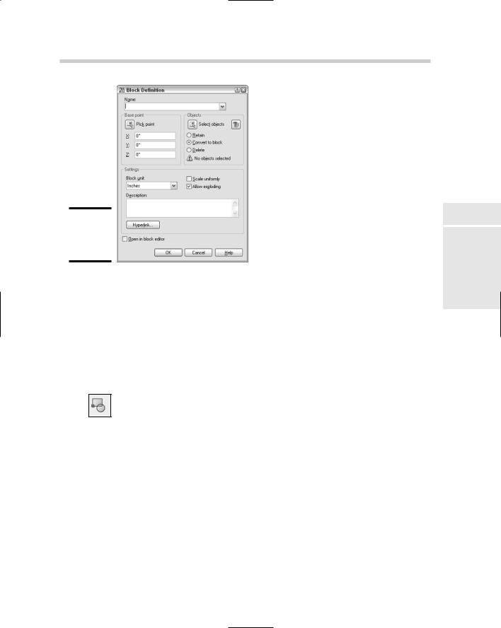
AutoCAD allows you to create a block directly from a drawing without the need of doing much else. To create a block, you use the BLOCK command to display the Block Definition dialog box (see Figure 1-1). When you create a block, you need to know three things:
Name. The text string that is used to specify which block to insert into the drawing.
Base point. The point on the block that will be used to help place it into the drawing when it is being inserted. This point is usually established on an object that is selected when creating a block, but it may not be based on how the block is inserted later in a drawing.
Objects. Which objects in the drawing should be a part of the block when it is created.