Wedge
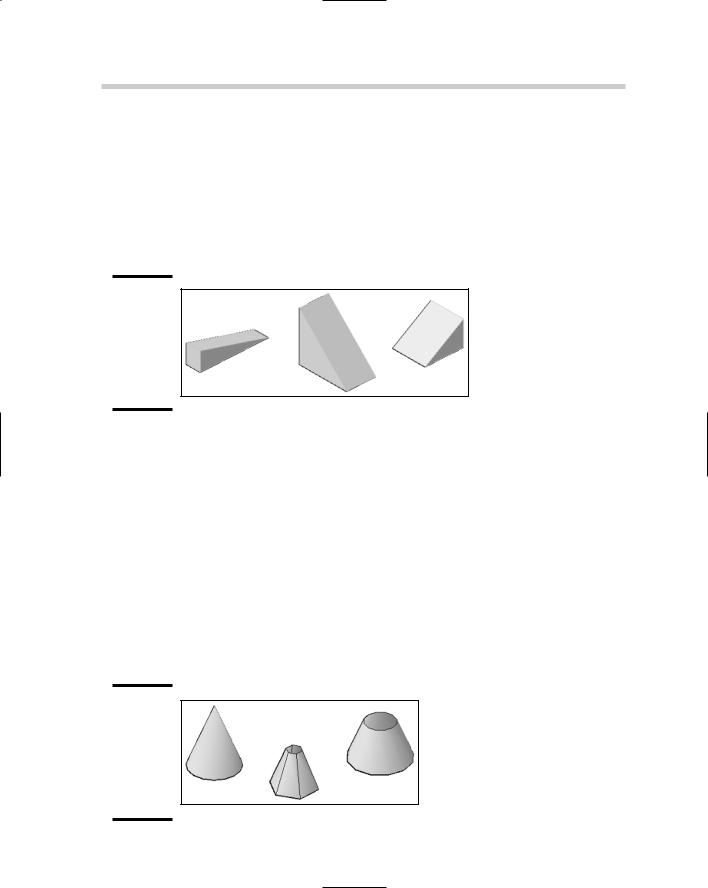
A wedge is created using the AI_WEDGE command and looks just like one created with the WEDGE command (see Figure 6-5), but they are edited in different ways. To start the AI_WEDGE command, you type the command in at the command line or the dynamic input tooltip. After the command starts, you specify the first corner of the wedge, its length and width, and finally its height. After the wedge is created, you have the option of rotating it along the z axis.
Figure 6-5:
Some of the wedges that can be created with the AI_WEDGE command.
Cone
A cone is created using the AI_CONE command and can be made to look similar to one created with the CONE command (see Figure 6-6), but both are edited in different ways. To start the AI_CONE command, you type the command in at the command line or the dynamic input tooltip. When the command starts, specify the center point for the base, and then the radius or diameter of the base. After you have defined the base size, define the radius of the top of the cone. A radius of zero creates a point, whereas a radius greater than zero creates a flat top. After the base and the top of the cone have been defined, specify the height of the cone. The last bit of information is the number of segments that the cone should be created with: The higher the number, the smoother it appears. You should stay roughly around 16 segments when possible, but the number increases as the cone gets larger to give it a smooth appearance. The highest value you can use is 32,767.
Figure 6-6:
Some of the cones that can be created with the AI_CONE command.
Torus
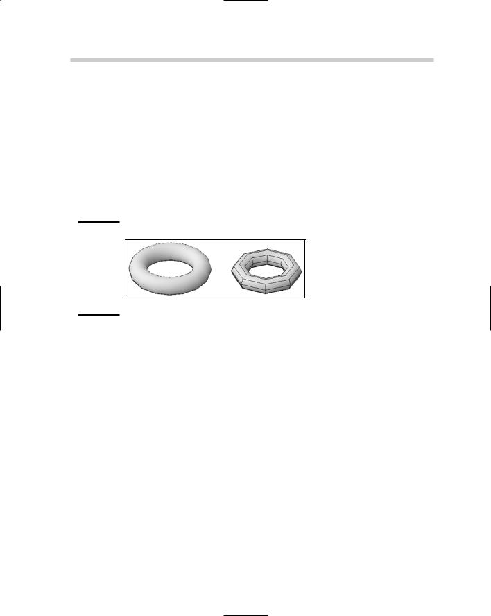
A torus that is created using the AI_TORUS command can be made to look similar to one created with the TORUS command (see Figure 6-9), but they are edited differently. To start the AI_TORUS command, type the command in at the command line or the dynamic input tooltip. When the command has been started, specify the center of the torus and then its radius or diameter. When the radius or diameter of the torus has been defined, define the radius or diameter of the torus’s tube. After the overall size and tube have been specified, specify the number of segments for the torus and the tube. The greater the number of segments specified, the smoother the torus appears.
Figure 6-9:
Two of the toruses that can be created with the AI_TORUS command.
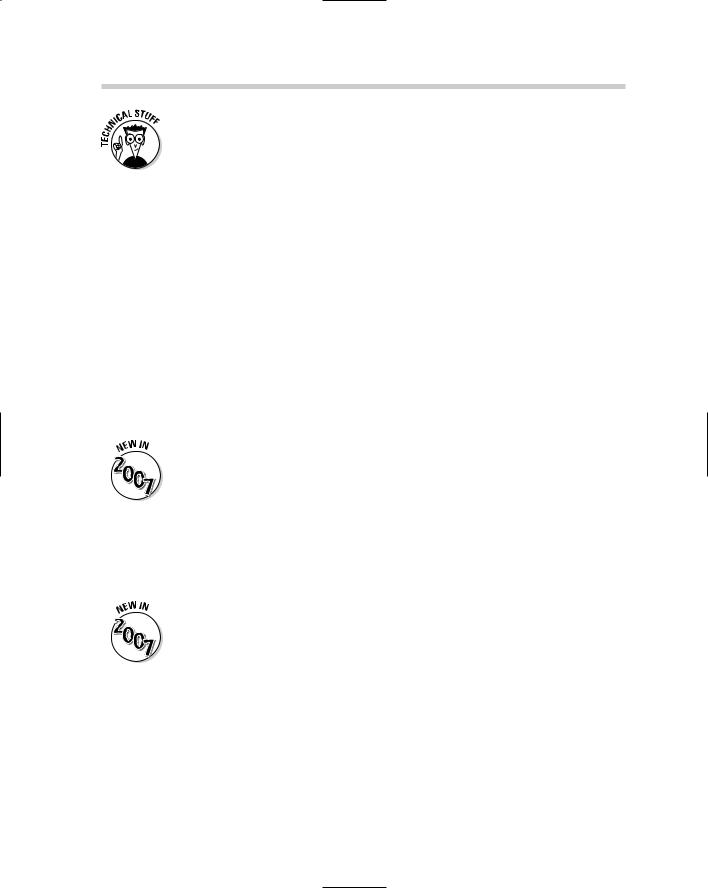
Pyramid
A pyramid that is created using the AI_PYRAMID command can be made to look similar to a threeor four-sided pyramid that is created with the PYRAMID command, but the AI_PYRAMID command offers variations that are not possible with the PYRAMID command (see Figure 6-10). The AI_PYRAMID command allows you to create a tetrahedron (three-sided
pyramid) or a four-sided pyramid, which can have a point, a ridge, or a flat top. To start the AI_PYRAMID command, you type the command in at the command line or the dynamic input tooltip. When the command has been started, you specify the first corner of the pyramid’s base, and then up to four other corners based on if you are creating a tetrahedron (three-sided pyramid) or a four-sided. After the base is defined, you can specify the location for the type of the pyramid’s top: either a point (apex), ridge, or a top. When you define the type of top for the pyramid, you are also defining its height.
336 Editing Surfaces
The system variables SPLFRAME controls the display of edges that have been set as invisible on a surface. Setting the variable to a value of 1 and doing a REGEN causes the edges that are invisible to be displayed on-screen.
Using grips to edit surfaces
Using grips with surfaces and meshes is much different than with solids. When you select a surface or mesh, a grip is displayed at each vertex that allows you to reposition the vertex. This causes the surface to become deformed or stretched, making it easier to blend surfaces and 3D solids together.
Working with convert to surface
AutoCAD allows you to take certain types of objects with specific property settings and convert them to surfaces: Some of these objects are 2D solids, regions, planar 3D faces, polylines that are open and have no width with thickness, and lines or arcs with thickness. To convert these objects to surfaces, you use the CONVTOSURFACE command. After the command is started and the object is created, a new Planar or Extruded surface is created. The CONVTOSOLID command allows you to take some objects with specific property settings and create extruded solids from them. For more information on these commands, refer to AutoCAD’s online Help system.
The CONVTOSOLID and CONVTOSURFACE commands are new in AutoCAD 2007.
Thicken
The THICKEN command is very similar to the EXTRUDE command, except it is limited to Planar and Extruded surfaces. To start the THICKEN command, choose Modify 3D Operations Thicken. After the command is started, select the Planar Surface that you want to thicken and specify a value for the thickness.
The THICKEN command is new in AutoCAD 2007.
Chapter 7: Rendering: Lights,
Cameras, AutoCAD!
In This Chapter
Adding lights into a scene
Placing materials on objects
Setting a background for a view
Rendering a scene
After you understand how to navigate, visualize, create, and edit 3D solids or surfaces, you can prepare your 3D model to be rendered.
Rendering allows you to present the concept to clients so they can visualize what the end product will look like when it is complete. Hidden line views and shaded views can help the client visualize the 3D model, but they lack the depth and realism that really sells a concept to a client. Before you generate a rendering, you add lights, materials, and a background to your 3D model. These all help bring realism to the 3D model to make it look like the final product. This chapter applies to AutoCAD only (not AutoCAD LT) and is designed to be an overview of lights, materials, backgrounds, and rendering a model. For more information on these topics, refer to AutoCAD’s online Help system.
Lighting a Scene
Lighting is a key to making your drawing — also known as a scene — look realistic because it gives variation to the colors in your model. Objects closest to the lights appear brighter, whereas objects that are farther from the light source appear darker. This is what happens in real life with light coming from the sun outside, or a lamp that is indoors. AutoCAD offers three types of lights: default lights, user lights (point, spotlight, and distant), and sunlight. All of these types of lights, with the exception of the default lights, can cast shadows. To help manage the creation and editing of lights, use the Light control panel on the Dashboard, the Sun Properties palette, and the Lights in Model palette.
The lighting system has been greatly improved in AutoCAD 2007 with better control over lights and shadows.
Default lights
Previous releases of AutoCAD had a single default light, which always shined in the direction of the current view. AutoCAD 2007 now has two default lights to help bring the level of lighting up and to balance the lighting on each side of the model. Default lighting does not cast shadows, so you shouldn’t use it for the final render, but it might be good enough for a conceptual drawing.
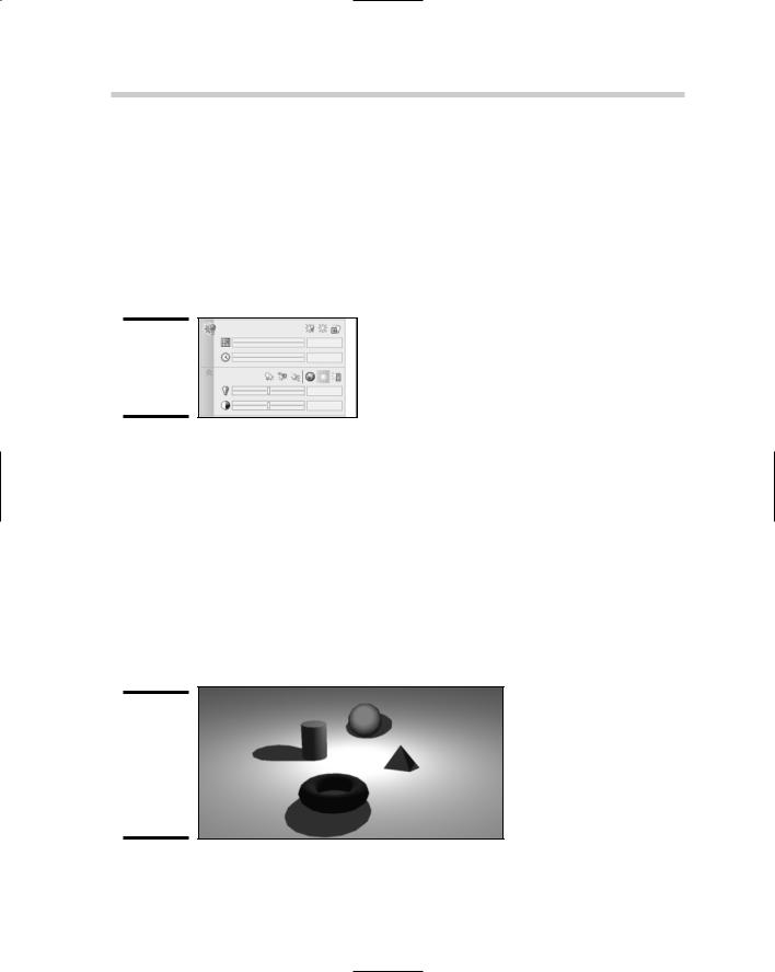
You do have some control over the brightness and contrast of the default lighting with the slider controls that are available when the Light control panel of the Dashboard palette is expanded (see Figure 7-1).
Figure 7-1:
The Light control panel of the Dashboard.
User lights
User lights are lights that you add to a scene. When you place user lights in a scene, you need to disable the default lights that AutoCAD automatically creates when a drawing is opened. User lights come in three distinct types of lights:
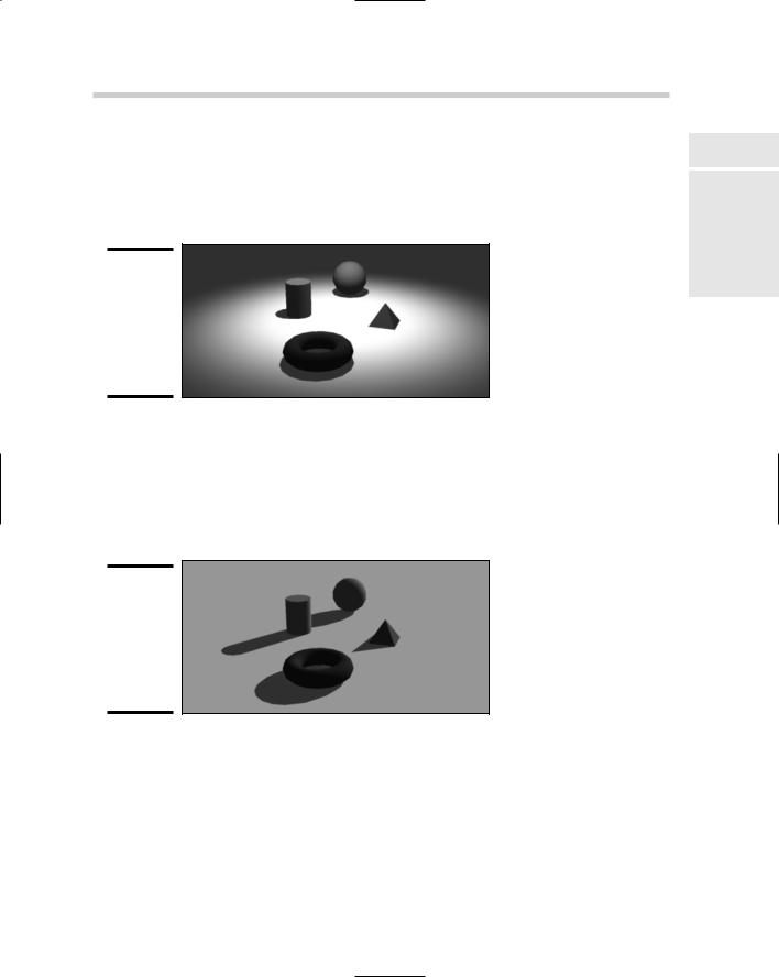
Point light: A point light emits light in all directions, but the light decays or falls off the farther you get from the light. The falloff defines at what point no more light is emitted; by defining the falloff value of the light, you can reduce rendering time. You can think of a point light as similar to a candle or a lamp. Figure 7-2 shows four objects illuminated by a single point light.
Figure 7-2:
Point light emitting light and casting shadows on objects in a scene.
buttons from the expanded part of the Light control panel of the Dashboard. Alternatively, choose View Render Light. After a light has been added to the scene, it can be modified with the Properties palette.
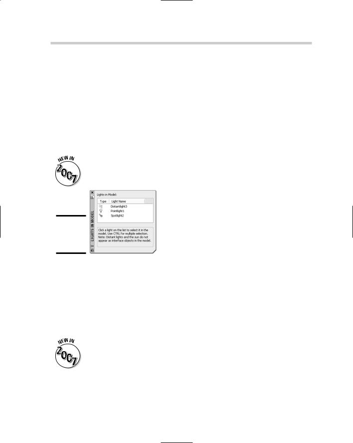
Point or spotlights can be selected and edited directly in a scene because a glyph is displayed to show where the light is located, unlike a distant light, which doesn’t have a glyph associated with it. (A glyph is a non-printing object displayed in a scene that enables you to modify an object that is not part of the actual design, such as a light or camera.) If the scene is complex or you need to select a distant light in the scene, you need to use the Lights in Model palette (see Figure 7-5). The Lights in Model palette allows you to select, delete, and access the Properties palette for editing the selected light(s). To display the Lights in Model palette, use the LIGHTLIST command, which can be accessed by choosing Tools Palettes Lights.
The LIGHTLIST command is new in AutoCAD 2007.
Figure 7-5:
The Lights in Model palette.
Sunlight
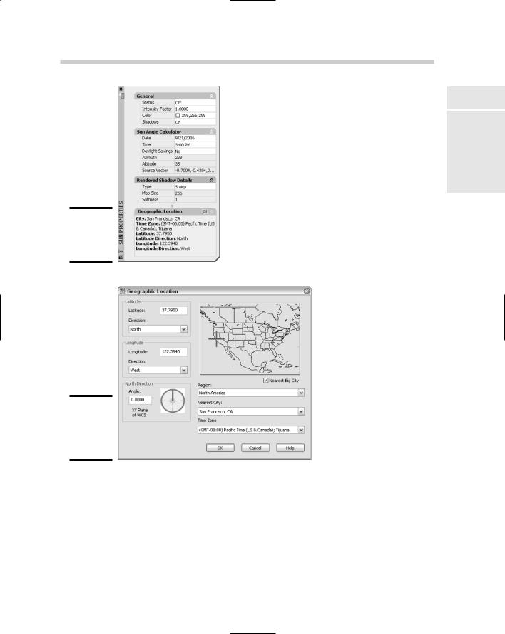
The ability to add light that is similar to sunlight is great for outdoor scenes, or for indoor scenes with light coming in through a window. Sunlight is controlled through the Sun Properties palette (see Figure 7-6) and the Geographic Location dialog box (see Figure 7-7). Both of these interfaces allow you to designate the position of the sun based on the city that your scene would be nearest to in the physical world, or at a specific latitude and longitude. You can also designate the Northern direction of the scene to make sure that light is emitting on the scene as it would after it was built.
The SUNPROPERTIES and GEOGRAPHICLOCATION commands are new in AutoCAD 2007.
Getting the Right Look with Materials 341
Figure 7-6:
The Sun Properties palette.
Figure 7-7:
The Geographic Location dialog box.
Book V
Chapter 7
Cameras,AutoCAD! |
Rendering:Lights, |
Getting the Right Look with Materials
Materials help to give your objects that special touch of realism, whether they are made up of metal, glass, plastic, or wood. Materials allow you to make the scene much more convincing to the viewer. The MATERIALS command is used to display the Materials palette (see Figure 7-8), which allows


