322 Creating Solid Primitives
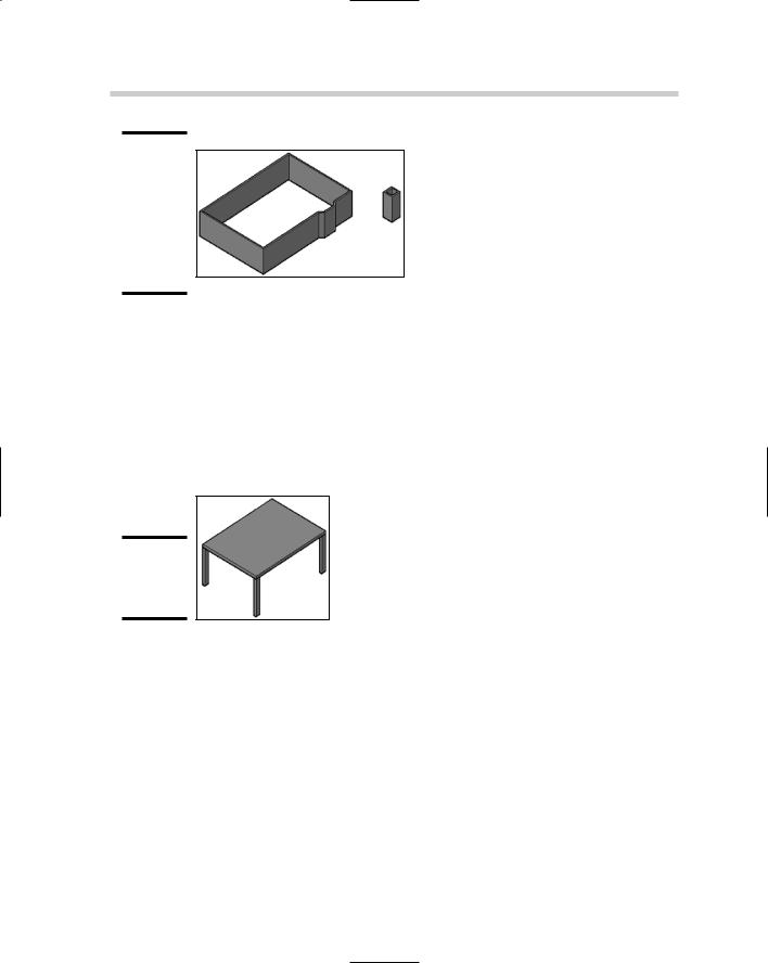
Figure 5-1:
The outline of a 2D floor plan converted to 3D walls with the POLYSOLID command.
Figure 5-2:
A table created from boxes.
Box
A box is a six-sided object that is either a cube or rectangular. A box could be used for virtually anything from a table (see Figure 5-2) to a door or even a building in the background of a conceptual drawing. To start the BOX command, choose Draw Modeling Box. After specifying the first corner or the center of the box, you can then finish defining the base of the box by selecting the opposite corner, creating a cube, or defining its length. Based on the option you select, you may need to define the box’s height.
Wedge
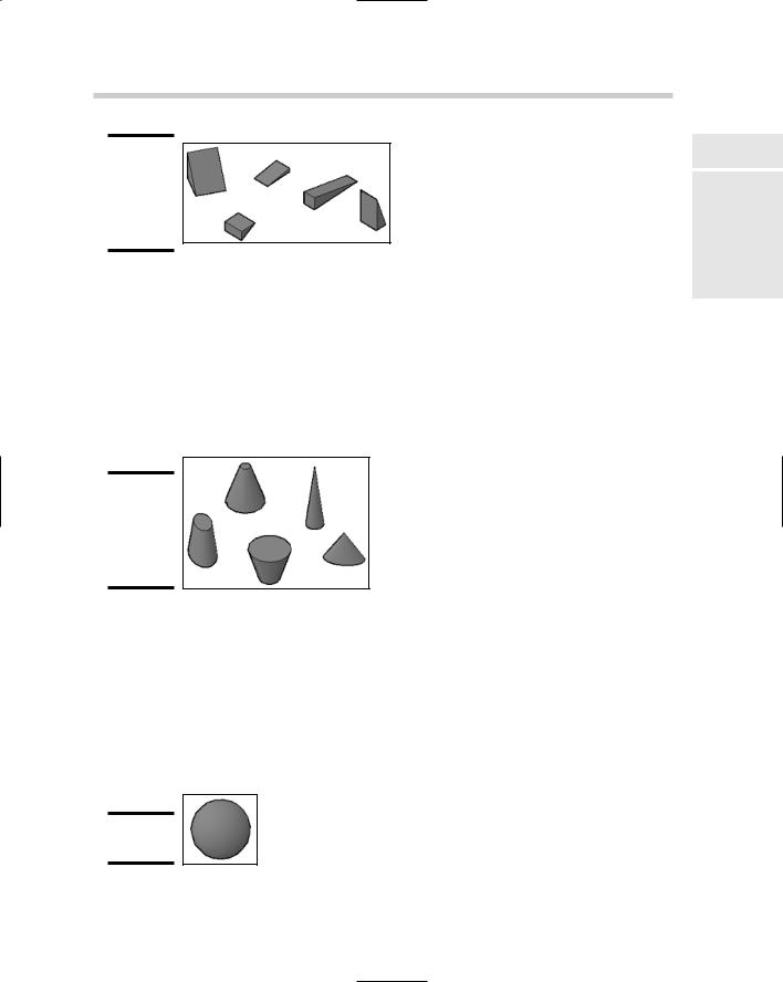
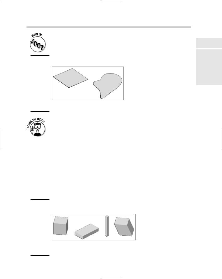
A wedge is half of a box diagonally from an upper edge to a lower edge. A wedge might be useful for creating a ramp, a roof slope, or even a slice of chocolate cake. Figure 5-3 shows some of the different sizes of wedges that can be created with the WEDGE command. To start the WEDGE command, choose Draw Modeling Wedge. After specifying the first corner or the center of the wedge, you can then finish defining the base of the wedge by selecting the opposite corner, creating a cube, or defining its length. Based on the option selected, you may need to define the wedge’s height.
Creating Solid Primitives 323
Figure 5-3:
Some different shapes and sizes of wedges.
Figure 5-4:
Some different shapes and sizes of cones.
Figure 5-5:
A sphere.
Cone
A cone is an object with a circular base that has either a point or a flat top. The base of a cone can be larger than its top and even be elliptical rather than circular. You might use a cone for a handle or pull, a cup, or a planter. Figure 5-4 shows some of the different sizes and types of cones that can be created with the CONE command. To start the CONE command, choose Draw Modeling Cone. After specifying the center of the cone’s base, specify the radius or diameter of the base and then its height.
Sphere
A sphere is a full circular object that is created from the very center of the object. The sphere is one of two types of 3D solids that is created half above and half below the current XY plane (see Figure 5-5). Torus is the other type of 3D solid created above and below the current XY plane, which we discuss later in this chapter in the section called “Torus.” To start the SPHERE command, choose Draw Modeling Sphere. After specifying the center of the sphere, you specify its radius or diameter.
Book V
Chapter 5
Workingwith Solids
324 Creating Solid Primitives
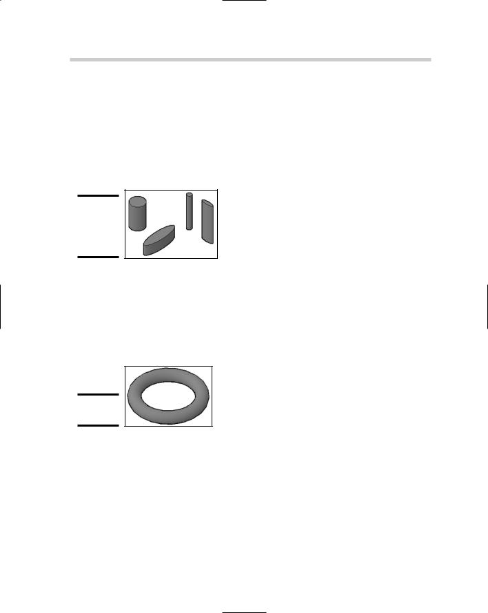
Figure 5-6:
Different shapes and sizes of cylinders.
Figure 5-7:
A torus.
Cylinder
A cylinder is a circle or ellipse with height and is commonly created from the center of the object. Cylinders can be used for a variety of things, like the legs of a table or chair, glasses, or a shaft for a gear. Figure 5-6 shows some of the different sizes and types of cylinders that can be created with the CYLINDER command. To start the CYLINDER command, choose Draw Modeling Cylinder. After specifying the center of the cylinder’s base, specify the radius or diameter of the base and then its height.
Torus
A torus is a 3D donut that is created from the very center of the object. The torus, like the sphere, is created half above and half below the current XY plane (see Figure 5-7). To start the TORUS command, choose Draw Modeling Torus. After specifying the center of the torus, specify its radius or diameter, and then the radius or diameter of the tube.
Pyramid
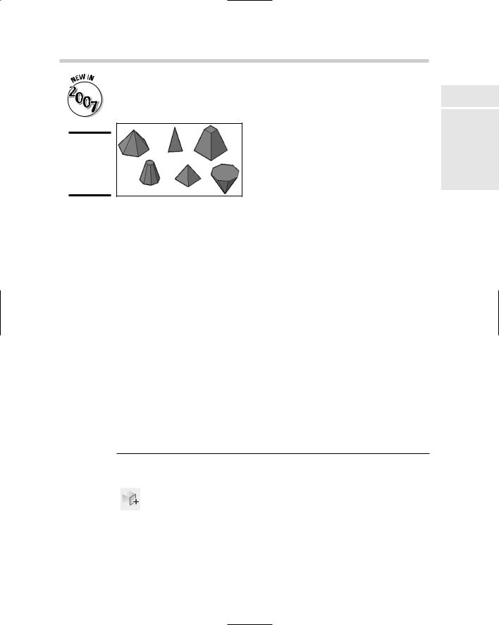
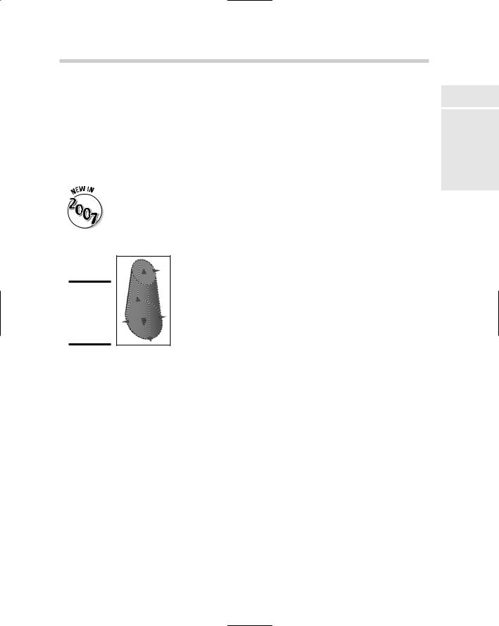
A pyramid is similar to a cone, except instead of a circular base, it has a polygon-shaped base that can have from 3 to 32 sides and either a point or a flat top. You might use a pyramid for the top of a building, base of a street sign, or even a light fixture. Figure 5-8 shows some of the different sizes and types of pyramids that can be created with the PYRAMID command. To start the PYRAMID command, choose Draw Modeling Pyramid. After you spec-
ify the center or the edge of the pyramid’s base, specify the radius or use the inscribed option and then its height.
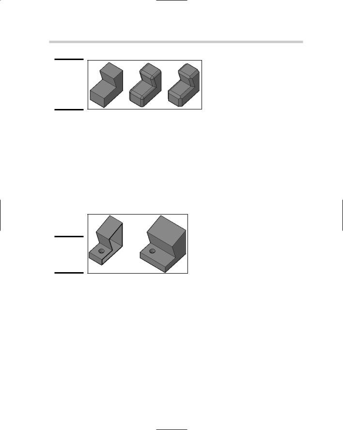
Figure 5-10:
A 3D solid before and after it was filleted and chamfered.
Slice
At times, you may only want a portion of the 3D solid for your model. In these cases, you can use the SLICE command. You can slice a 3D solid using a planar object like a circle, ellipse, 2D polyline, or a surface, among many others. You can keep both halves of the solid after it has been sliced, or whichever side you want to keep. Figure 5-11 shows a solid that has been sliced in half. To start the SLICE command, choose Modify 3D Operations Slice. After you specify the 3D solid to slice, you specify the axis or object you want to use as the cutting plane and then you decide which part of the resulting objects to keep.
Figure 5-11:
A 3D solid sliced in half.
Chapter 6: Working with Surfaces
In This Chapter
Creating surfaces
Editing surfaces
In the previous chapter, we cover creating and modifying 3D solids. This chapter takes a similar look at creating and modifying surfaces. Many
commands allow you to create primitives out of surfaces instead of a 3D solid. Surfaces take a little more planning to create and modify than 3D solids do, but they do have advantages, depending on what you are trying to model.
Creating Surfaces
AutoCAD offers a variety of commands that allow you to create primitives as surfaces, which are similar to the commands that allow you to create 3D primitives. Just like the primitive 3D solids, surfaces help to form the foundation of 3D modeling in AutoCAD. Surfaces are not as easy to modify as 3D solids are, but you can deform and change their shapes much more easily than you can a 3D solid. Most of the primitives that can be created as 3D solids can be created with surfaces through the use of the 3D command or a command that is specific to the primitive.
3D face
A surface can be either threeor four-sided. Most of the commands in this chapter create meshes that are composed of multiple surfaces to create a primitive. The 3DFACE command allows you to create a single threeor foursided surface (see Figure 6-1). As you create a surface with the 3DFACE command, you can control which sides of the surface are visible when the model is viewed as hidden, shaded, or rendered. To start the 3DFACE command, choose Draw Modeling Meshes 3D Face. After specifying the first corner, you specify two more points and then press Enter to create a three-sided surface, or specify a fourth point to create a four-sided surface. You can continue to specify additional points to create additional surfaces. As you specify points, you can toggle the visibility of the edge that is created.
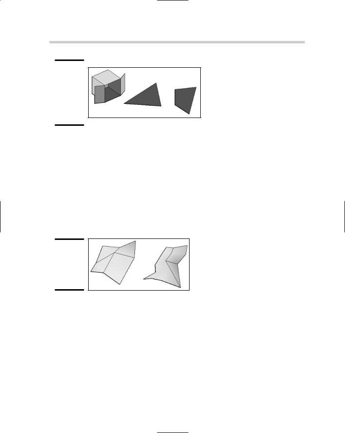
Figure 6-1:
An open box created with surfaces, and a threeand foursided surface.
3D mesh
A mesh is a group of vertices that form a particular pattern to create a group of surfaces based on the number of vertices specified (see Figure 6-2). If a mesh is exploded, the result is individual surfaces that are created between the specified vertices. A mesh is commonly created as an open object, but can be closed through the use of the PEDIT command. To start the 3DMESH command, choose Draw Modeling Meshes 3D Mesh. After you start the 3DMESH command, you are prompted to specify the size in the M and N directions, which determines the number of vertices that you are prompted for. After the M and N directions have been specified, you specify all the vertices to create the mesh.
Figure 6-2:
A couple of meshes created with the 3DMESH command.
Planar surface
A planar surface is an object that can be created by specifying two corners to form a rectangular object, or selecting objects that form a closed object just like the region command does (see Figure 6-3). Unlike many of the commands that create surfaces and meshes in this chapter, exploding a planar surface results in the creation of a region. To start the PLANESURF command, choose Draw Modeling Planar Surface. After you start the PLANESURF command, you are prompted to specify the first corner of the planar surface and then the opposite corner, which creates the planar surface on the xy plane. Alternatively, you are prompted to select a closed object.

