312 Creating 3D Objects from 2D Objects
Figure 4-3:
The results of extruding open and closed objects.
Loft
Loft allows you to create a solid or a surface based on a series of specified cross-sections. The cross-sections are used to define the profile that is generated, and you must use a minimum of two cross-sections for the loft. If you use open objects for the cross-sections, the resulting loft is a surface; if you use closed objects for the cross-sections, the resulting loft is a solid. You can loft objects along a path by using guides or just the selected cross sections (see Figure 4-4). To start the LOFT command, select the Draw menu on the menu bar, and then choose Modeling Loft.
The LOFT command is new in AutoCAD 2007.
Figure 4-4:
The results of lofting objects using crosssections only.
Sweep
Sweep is very similar to Loft except you use a single cross-section instead of two or more. The cross-section is used to define the profile that is generated. If you use an open object for the cross-section, the resulting sweep is a surface; if you use a closed object for the cross-section, the resulting sweep is a solid. You sweep the selected objects along a path (see Figure 4-5). To start the SWEEP command, select the Draw menu on the menu bar, and then choose Modeling Sweep.
The SWEEP command is new in AutoCAD 2007.
Creating 3D Objects from 2D Objects 313
Figure 4-5:
The results of sweeping objects along a path.
Revolve
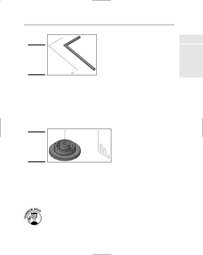
Revolve allows you to create a solid or a surface based on selected objects and a specified axis that they should revolve around. If you use open objects, the resulting revolve is a surface; if you use closed objects, the resulting revolve is a solid. You revolve the selected objects around an axis and specify the angle at which you want the objects to be revolved (see Figure 4-6). To start the REVOLVE command, select the Draw menu on the menu bar, and then choose Modeling Revolve.
Figure 4-6:
The results of revolving objects along an axis.
Tabulated Mesh
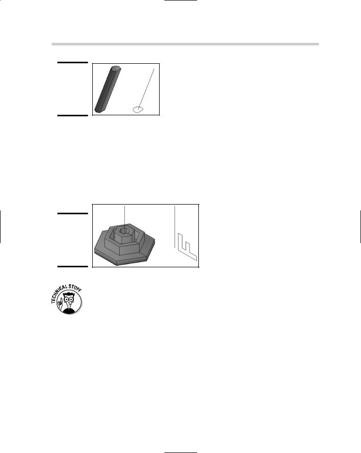
Tabulated Mesh allows you to create a mesh based on a profile (path curve) and a direction vector. Unlike some of the previously mentioned commands in this section, such as extrude and loft, a closed profile doesn’t create a solid. You extrude the selected object (path curve) along a selected path (see Figure 4-7). To start the TABSURF command, choose Draw Modeling Meshes Tabulated Mesh.
TABSURF uses the value of the system variable SURFTAB1 to control the number of segments that the mesh is created with. The higher the number, the smoother the mesh looks, and the better it follows the selected object (path curve). By default, SURFTAB1 is set to a value of 6.
314 Creating 3D Objects from 2D Objects
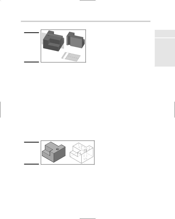
Figure 4-7:
The results of using TABSURF on a closed object.
Figure 4-8:
The results of using REVSURF on a closed object.
Revolved Mesh
Revolved Mesh is similar to Revolve, except you are only able to select a single object with Revolved Mesh, and a mesh is created even when a closed object is selected. After you select the object you want to revolve, you specify the axis by selecting an object, and then you specify the start and include angles to revolve the object around the axis (see Figure 4-8). To start the REVSURF command, choose Draw Modeling Meshes Revolved Mesh.
REVSURF uses the values of the system variables SURFTAB1 and SURFTAB2 to control the number of segments that the mesh is created with. The higher the number, the smoother the mesh looks and the better it follows the selected object. By default, SURFTAB1 and SURFTAB2 are set to a value of 6.
Ruled Mesh
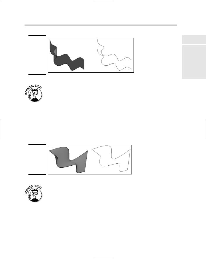
Ruled Mesh allows you to create a mesh between two selected objects. You can use both open and closed objects with the command, but if you use a closed object, the other object must also be a closed object. Ruled Mesh is similar to the way loft works because a new object is created based on the selection of two profiles (see Figure 4-9). To start the RULESURF command, choose Draw Modeling Meshes Ruled Mesh.
Creating 2D Objects from 3D Objects 315
Figure 4-9:
The results of using RULESURF on two splines at different elevations.
RULESURF uses the value of the system variable SURFTAB1 to control the number of segments that the mesh is created with. The higher the number, the smoother the mesh looks and the better it follows the selected object. By default, SURFTAB1 is set to a value of 6.
Edge Mesh
Edge Mesh allows you to create a three-dimensional mesh that follows the edges of four objects. The objects must be open objects, but their end points must match up with each other. The edges must be selected in a specific order to properly generate the mesh (see Figure 4-10). To start the EDGESURF command, choose Draw Modeling Meshes Edge Mesh.
Figure 4-10:
The results of using EDGESURF on four objects.
EDGESURF uses the values of the system variables SURFTAB1 and SURFTAB2 to control the number of segments that the mesh is created with. The higher the number, the smoother the mesh looks and the better it follows the selected object. By default, SURFTAB1 and SURFTAB2 are set to a value of 6.
Creating 2D Objects from 3D Objects
AutoCAD allows you to make the transition from 2D to 3D without having to completely abandon what you already know about 2D drafting. Wouldn’t it be nice to be able to create a 2D representation of the 3D model that you
316 Creating 2D Objects from 3D Objects
spent numerous hours creating? You’re in luck: AutoCAD comes with commands that allow you to take your 3D model and generate a 2D representation of a given view. After you have a 2D representation of the 3D model, you can then add any dimensions and notes necessary for construction or manufacturing.
Flatshot
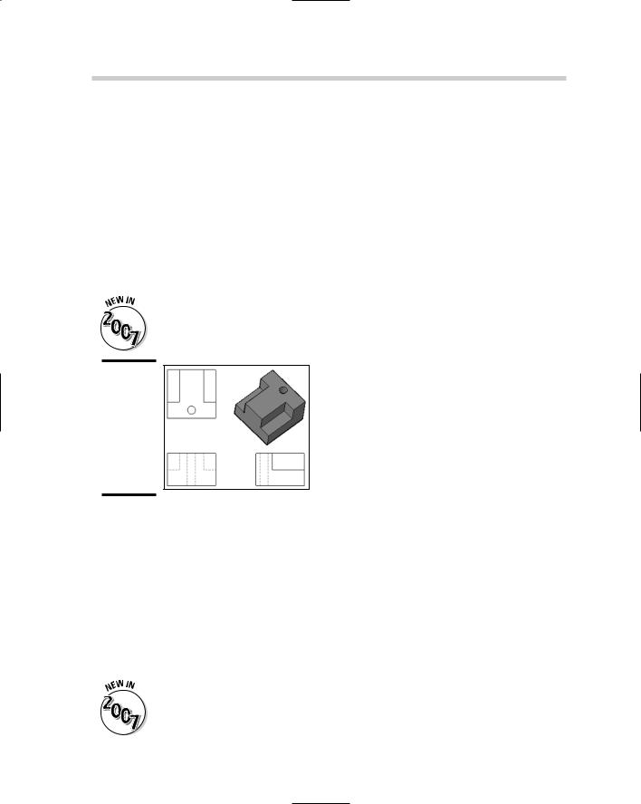
Flatshot allows you to create a block that contains 2D objects based on the current view of a 3D model. By creating the 3D model first, you can create a block that contains only the objects that are visible in that view, or include the obscured lines in a different color or linetype (see Figure 4-11). Flatshot looks for all 3D objects that are in the current view and ignores all 2D objects. To start the FLATSHOT command, select Flatshot from the 3D Make control panel on the Dashboard palette.
The FLATSHOT command is new in AutoCAD 2007.
Figure 4-11:
The results of creating three different views from one model with Flatshot.
Section Plane
Section Plane allows you to cut a 3D solid without actually altering the object itself to generate a 2D or 3D object based on the geometry along the defined plane (see Figure 4-12). This allows you to quickly create different views of a model to help manufacture it, or even assemble it. Unlike Flatshot, a Section Plane can go through an object and be able to generate a 2D representation of the objects that are along the Section Plane. To create a 2D or 3D representation of the objects along a plane, you first start the SECTIONPLANE command, and then choose Draw Modeling Section Plane. After the Section Plane has been created, you have various different options of how you want to display the objects around the Section Plane. The options can be accessed from the right-click shortcut menu or the Properties palette.
The SECTIONPLANE command is new in AutoCAD 2007.
commands can be used on solids, surfaces, and even 2D objects. All of these commands are located under the 3D Operations submenu of the Modify menu on the menu bar.
3D Move
The 3D Move command allows you to move selected objects along the xy plane and in the z direction. This command uses what is called a grip tool to allow you to restrict or constrain movement along an axis (see Figure 4-14). The command prompts are identical to the MOVE command, so using the 3D Move command should be familiar. The 3DMOVE command can be started by selecting 3D Move from the 3D Operations submenu under the Modify menu on the menu bar.
The 3DMOVE command is new in AutoCAD 2007.
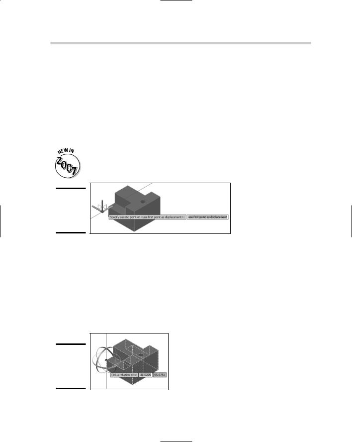
Figure 4-14:
The grip tool for the 3DMOVE command.
3D Rotate
The 3D Rotate command allows you to rotate selected objects along the x, y, or z axis. Like the 3D Move command, the 3D Rotate command uses a grip tool to allow you to restrict or constrain the rotation along an axis (see Figure 4-15). The command prompts are similar to the ROTATE command, with one slight difference: You need to pick an axis for rotation, and then a start and end angle instead of just a rotation angle. The 3DROTATE command can be started by selecting 3D Rotate from the 3D Operations submenu under the Modify menu on the menu bar.
Figure 4-15:
The grip tool for the 3DROTATE command.
Chapter 5: Working with Solids
In This Chapter
Creating solid primitives
Editing solids
In the previous chapter, we covered many of the commands that allow you to take the knowledge that you already have about 2D drafting and
apply it to 3D. In this chapter, you discover many of the 3D commands that allow you to create and edit 3D objects. AutoCAD allows you to create 3D objects known as primitives. Primitives are very basic objects like boxes, cones, and spheres that can be used to create complex models. You also find out more about modifying commands that are used to manipulate
a 3D solid.
Creating Solid Primitives
AutoCAD offers a pretty good variety of primitive 3D objects that can be used to create complex models. The primitive objects help to form the foundation of 3D modeling in AutoCAD: You can combine these primitives with other primitives or even manipulate a primitive so that it is filleted (with rounded edges), shelled (hollowed out), and more.
Polysolid
A polysolid is very similar to a 2D polyline, except it has a single uniform width and a height. Polysolid is great for creating 3D walls to create a conceptual look of a building (see Figure 5-1) or for creating rectangular duct work. To start the POLYSOLID command, choose Draw Modeling Polysolid. After you start the POLYSOLID command, you can draw a polyline-like object that allows you to create both straight and curved segments. If you already have lines, arcs, and polylines in your drawing, you are able to convert those to solid with the Object option of the POLYSOLID command. You are also able to specify the height, width, and justification for how the new solid object is created.