Добавил:
Опубликованный материал нарушает ваши авторские права? Сообщите нам.
Вуз: Предмет: Файл:

AutoCAD & AutoCAD LT All-In-One Desk Reference For Dummies (2006)

.pdf
Скачиваний:
90
Добавлен:
17.08.2013
Размер:
17.7 Mб
Скачать

302 Navigating a 3D Model

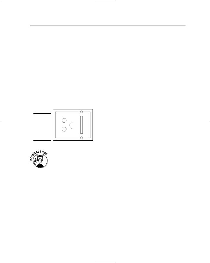
While one of the 3D orbit commands (or any of the other 3D navigation commands that we mention in the next section) is running, you can right-click and access the Navigation Modes menu (see Figure 3-6). This menu allows you to switch between Parallel and Perspective view, between different visual styles, or even to other navigation commands without having to exit one command in order to start another. You can also switch to a different navigation command by pressing the number next to it under the Other Navigation Modes submenu.

Figure 3-6:

The Navigation Modes menu.

If you hold down the Shift key first and then press and hold down the middle mouse button, you can temporarily switch to 3DORBIT. Pressing and holding the middle mouse button and then pressing the Shift key temporarily places you in orthogonal pan mode.

If the drawing contains a lot of objects, you can select a small set of the objects before starting one of the 3D orbit commands. This can help with performance in larger drawings because only the selected objects appear while the 3D orbit command is in use.

Navigating a 3D Model

AutoCAD offers other 3D navigation commands besides just the 3D orbit commands. Both zoom and pan are offered in 3D versions, but you can still use other zoom options such as window and extents. However, a few additional commands are used specifically for 3D navigation. These commands

Navigating a 3D Model 303

make it feel like you are right in your drawing. The 3D navigation commands can be accessed from the View menu on the menu bar, under the submenus Camera Walk and Fly, or on the 3D Navigation toolbar.

AutoCAD LT does not support the 3D navigation commands listed below.

AutoCAD 2007 offers two new 3D navigation commands called 3DWALK and 3DFLY.

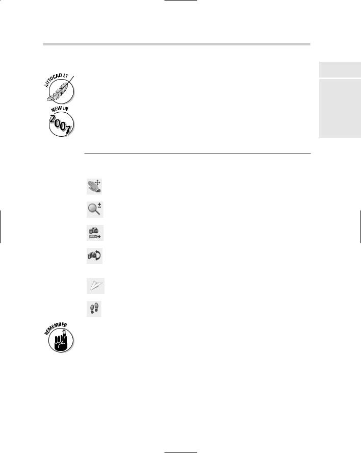
Table 3-2 lists the other 3D navigation commands that are available in AutoCAD.

Table 3-2


3D Navigation Commands

Icon

Command

Description


3DPAN

Allows you to interactively drag the view vertically, horizon-


tally, and diagonally.


3DZOOM

Allows you to move the camera closer to or farther away


from the target, making objects appear closer or farther


away.


3DDISTANCE

Allows you to pull or push yourself in and out of the drawing


by making objects come closer or go farther away from you.


3DSWIVEL

Allows you to change the target of the view you are currently


looking at in the drawing. Makes it feel like you are turning


your head around in the drawing to view other objects while


standing in a single spot.


3DFLY

Allows you to interactively change the view of the drawing as


you “fly” through it. You leave the xy plane to give you the feel


that you are above the drawing.


3DWALK

Allows you to interactively change the view of the drawing as


you “walk” through it. You remain on the xy plane to give you


the feel that you are walking through the drawing.


When using one of the 3D navigation commands, you can right-click and choose a different navigation mode from the shortcut menu.

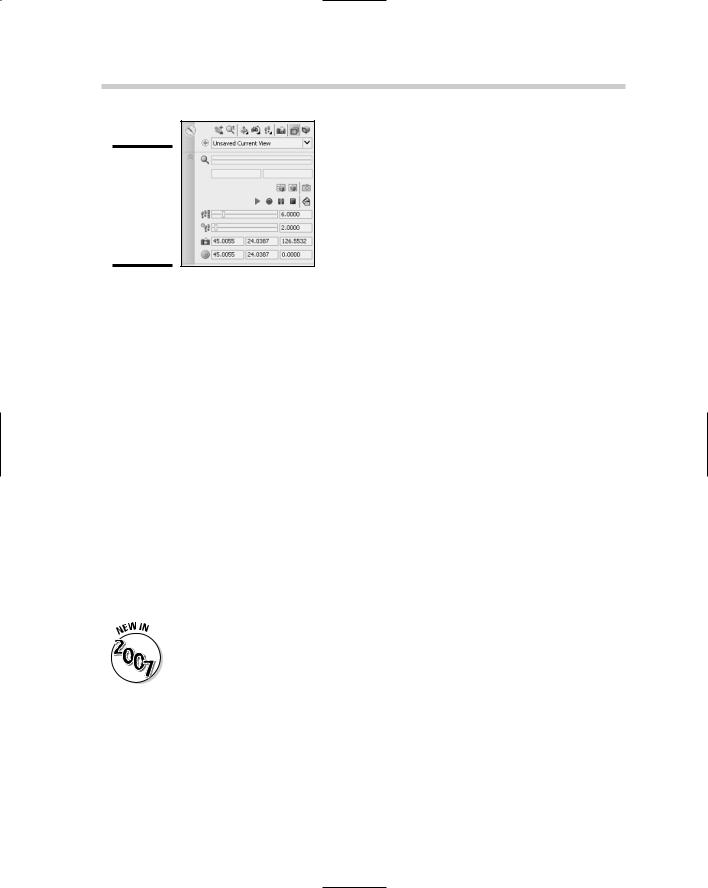
Many of the 3D navigation commands and settings can be accessed directly from the 3D Navigation control panel (see Figure 3-7) of the Dashboard palette. Some of the settings are hidden at first; if you position the cursor over the control panel, an icon with double down arrows appears. Click the double down arrows icon to expand the control panel.

Book V

Chapter 3

in Viewing 3D

304 Adding Some Color and Style to a 3D Model

Figure 3-7:

The 3D Navigation control panel of the Dashboard palette.

Adding Some Color and Style to a 3D Model

Looking at drawings that are displayed in 2D and 3D wireframe can make it rather difficult to visualize what is actually in there. AutoCAD and AutoCAD LT offer a few options to help you see what all of those lines actually mean. AutoCAD uses visual styles to display geometry so you only see the objects that are in front of others. AutoCAD LT doesn’t support visual styles but instead has a feature called shade modes. Shade modes were available in previous releases of AutoCAD to hide faces that are not those closest to the current viewpoint.

Visual styles in AutoCAD

Visual styles allow you to see your drawing in a hidden, shaded, or semirendered state. Visual styles are available from the Visual Styles Manager palette or the Visual Style control panel on the Dashboard palette. To display the Visual Style Manager palette (see Figure 3-8) from the menu bar, choose Tools Palettes Visual Styles. Double-click one of the available visual styles to set it current. You can also make a custom visual style and make changes to it by changing its properties at the bottom of the palette. You can set a visual style current when drawing to give you a sense of what lines you might want to snap to.

Visual styles are new in AutoCAD 2007, and they make it much easier to get different looks to a 3D model for presentation purposes.

The Visual Style control panel (see Figure 3-9) on the Dashboard palette contains a variety of controls that allow you to change to a different visual style, enable x-ray mode to see through faces, control how faces and edges are displayed, and even the display of shadows in a scene.

Adding Some Color and Style to a 3D Model 305

Figure 3-8:

Visual styles give a 3D model personality.

Figure 3-9:

The Visual Styles control panel of the Dashboard palette.

Book V

Chapter 3

in Viewing 3D

Shademode in AutoCAD LT

AutoCAD LT doesn’t support the use of visual styles, but you can do a few things to get a similar effect when viewing a 3D model. AutoCAD LT offers a command called SHADEMODE, which allows you to view a model in 2D wireframe or hidden line view. SHADEMODE is similar to a visual style in most ways, with the exception that it cannot customize its appearance. AutoCAD LT also offers the SHADE command, which allows you to shade a

3D model based on the colors that the objects are assigned, and you can use the HIDE command to display a 3D model in a hidden line view. The SHADE and HIDE commands are available from the View menu on the menu bar. SHADEMODE must be typed in at the command line or the dynamic input ToolTip; next, select the option you want to use.

306 Book V: 3D Modeling

Chapter 4: Moving from 2D to 3D

In This Chapter

Working with regions

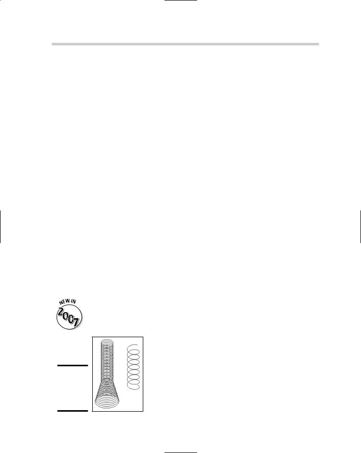
3D polylines and helixes

Creating 3D objects from 2D objects

Creating 2D objects from 3D objects

3D modify commands

After you figure out how to get around a drawing, it’s time to create some objects. First, you start off by creating 2D objects. (Yes, you read that

correctly: 2D objects.) Although the result you want is a 3D model, you don’t have to create everything using just 3D objects. Taking what you already know about creating 2D objects and applying that knowledge to 3D modeling helps you feel more comfortable with using and working in 3D. AutoCAD provides some tools that can help you create 2D views of the 3D model so you can generate the necessary shop drawings to get the model built.

At the end of this chapter, we cover some of the common 3D modify commands to help position 3D objects. Most of this chapter applies to AutoCAD only (not AutoCAD LT) and is designed to give you an overview of the different commands that allow you to go from 2D to 3D and back again.

(An entire book could be written on just working with AutoCAD 3D alone.) For more information on the commands in this chapter, refer to the AutoCAD online Help.

Working with Regions

Regions are 2D objects that are created from closed shapes — or loops. A loop is a set of objects like lines and arcs that form a closed object but are not necessarily a closed object themselves, like a circle, polyline, or spline. You can create a region of polylines, lines, arcs, circles, elliptical

arcs, ellipses, and splines. Regions can be great for creating complex areas to hatch, and can be used to create 3D objects. You can obtain centroid (the center point of the mass or volume of a region), moment of inertia (the value used to calculate distributed loads), and other information about a region using the MASSPROP command, like you can with 3D solids. For more information on the MASSPROP command, see the section “Getting more information about regions.”

308 Working with Regions

Creating regions

Because regions are created from existing objects in a drawing, you first must create the closed objects or loops and then use the REGION command to generate a region out of them. A region is created for each closed object or loop that is selected. To start the REGION command, you can select Region from either the Draw menu on the menu bar or the Draw toolbar. An example of the REGION command follows, along with the objects that were selected (see Figure 4-1):

Command: _region

Select objects: Select the closed objects or loops

Specify opposite corner: 8 found Select objects: Press Enter

6 loops extracted.

6 Regions created.

Figure 4-1:

Closed objects converted to regions.

When you use the REGION command (and some of the other commands that are covered in this chapter), the original objects that you select to create the region or 3D object from are deleted automatically. To keep the original objects from being deleted, set the system variable DELOBJ to a value of 0.

Modifying regions

Regions are interesting objects because they are no longer 2D objects, nor are they 3D objects, so you modify them in a slightly different way. Although regions are not 3D objects, some of the 3D modify commands can be used on them. If you want to remove a portion of a region with another region, you wouldn’t use the TRIM command; instead, you would use the SUBTRACT command. You can use the EXPLODE command to convert a region back to 2D objects.

Union

Union allows you to combine two or more regions into a single region. This allows you to create very complex 2D objects that can later be extruded to create a 3D object. A great example of this is a metal plate that is used to

Working with Regions 309

keep an object in place, or the side panel of a desk. The UNION command is available from the Solid Editing submenu under the Modify menu or the Solid Editing toolbar.

Subtract

Subtract allows you to remove a region from another region that it intersects or overlaps. This allows you to create holes, slots, or notches in regions before you extrude them to create a 3D object. The SUBTRACT command is available from the Solid Editing submenu under the Modify menu or the Solid Editing toolbar.

Intersect

Intersect allows you to keep only the part of two overlapping or intersecting regions that intersect. Using intersect is much more common when you are working with 3D solids. The INTERSECT command is available from the Solid Editing submenu under the Modify menu or the Solid Editing toolbar.

Getting more information about regions

Regions are complex objects that can be used to construct 3D solids or 2D objects that can be used to calculate additional information for the design, such as area and perimeter. The MASSPROP command allows you to obtain more information about a 2D region or 3D solid than what the LIST command displays. To start the MASSPROP command, choose Tools Inquiry Region/ Mass Properties. An example of the MASSPROP command is

Command: _massprop


Select objects: Select a region(s)


Specify opposite corner:

1 found


Select objects: Press

Enter


---------------- REGIONS

----------------

Area:


37.3681


Perimeter:


26.4645


Bounding box:

X:

15.9560

--

24.1580


Y:

6.3739

--

11.4041

Centroid:

X:

19.7700


Y:

9.0755


Moments of inertia:

X:

3150.3487


Y:

14801.8030


Product of inertia:

XY:

6725.9145


Radii of gyration:

X:

9.1818


Y:

19.9025


Principal moments and

X-Y directions about centroid:

Book V

Chapter 4

2Dto

Moving

3D

from

310 3D Polylines and Helixes

I:68.9979 along [0.9864 0.1644]

J:199.8441 along [-0.1644 0.9864]

Write analysis to a file? [Yes/No] <N>: Press Enter

3D Polylines and Helixes

Although a line object is not in one sense a 3D object, lines can have a different starting and ending z coordinate value, which makes it a 3D command. The 3DPOLY command allows you to draw 3D polylines, and the HELIX command allows you to create 2D and 3D spirals. These are not in one sense the same as a solid or a surface, but they can be created with varying different z coordinate values without the need to change the current user coordinate system (UCS). For more information on the UCS, see Book V, Chapter 2.

3D polyline

3D polylines are very similar to the 2D polylines that you are already familiar with, with the exception that they support only straight segments, and a different z coordinate value can be specified for the start and end point of a segment. You use the 3DPOLY command to create a 3D polyline, which can be started by choosing Draw 3D Polyline, or entering 3DPOLY at the command line or dynamic input tooltip.

Helix

Helixes can be used to create 2D and 3D spirals, shown in Figure 4-2, that might be used to represent springs, coils, or even door stops. To create a 2D helix, use a height value of 0. Use the HELIX command to create a helix. The HELIX command is started by selecting Helix from the Draw menu on the menu bar, or entering HELIX at the command line or dynamic input tooltip.

The HELIX command is new in AutoCAD 2007and is not supported in AutoCAD LT.

Figure 4-2:

Helixes can be used to create springs.

Creating 3D Objects from 2D Objects 311

Creating 3D Objects from 2D Objects

AutoCAD’s roots started with 2D drafting. That continues to be the primary focus of the program, but Autodesk has shifted to making sure that 3D is a key part of the program. Because AutoCAD started off being a 2D drafting package, you can take your knowledge of 2D drafting to create 3D objects with it. This section discusses many of the different commands that allow you to take existing 2D objects and convert them into 3D objects. Some work with 2D profiles, whereas others might require you to create a region first or some sort of closed object. Everything in this section applies to AutoCAD only, with the exception of the Thickness section.

Thickness

Thickness is a property of most 2D objects, such as lines and circles. When you change the thickness of a 2D object, you are creating a surface out of the object, or a set of surfaces. These surfaces hide objects behind them, unlike wireframe models. If you add thickness to a circle, a cylinder is created that is capped on the top and bottom. Changing the thickness of a pline that has a width is a quick way to create a 3D wall. Thickness is also a system variable that can be set by typing THICKNESS at the command line or dynamic input ToolTip and entering a new value. New objects will be given the new thickness value.

Extrude

Extrude allows you to take an open or closed 2D object and create a solid or surface out of it. When you extrude a closed 2D object such as a polyline, spline, ellipse, circle, or region, you create a solid. If you extrude an open 2D object such as a polyline, spline, line, arc, or elliptical arc, you create a surface. Figure 4-3 shows the results of extruding an open and a closed object. You can extrude a face on a solid by holding down the Ctrl key and selecting the face when asked to select objects to extrude.

After you select the objects or faces you want to extrude, you specify a distance and direction to create the extrusion in. During the extrusion, you can select a path to extrude along which can be a 2D object or an edge of a solid or surface. To start the EXTRUDE command, choose Draw Modeling Extrude.

AutoCAD 2007 allows you to extrude open objects and generate surfaces from them.

If you want to keep the original object that is used to create the extruded object, set the system variable DELOBJ to 0.

Book V

Chapter 4

2Dto

Moving

3D

from