

AutoCAD & AutoCAD LT All-In-One Desk Reference For Dummies (2006)
.pdf292 Using the Coordinate System for 3D Drawing
Figure 2-7:
Changing the appearance of the UCS icon with the UCS Icon dialog box.
You can control where and if the UCS icon is displayed on-screen by using the following options.
Hide/Show the UCS icon: You can toggle the display of the UCS icon by choosing View Display UCS Icon On.
Display the UCS icon at the origin: You can toggle the display of
the UCS icon at the origin of the drawing by choosing View Display UCS Icon Origin. If the UCS can’t be displayed at the origin, AutoCAD places it in the lower-left corner of the drawing window.
Display the UCS icon in 2D or 3D visual styles: You can control whether the UCS icon is displayed when the model is being viewed with a 2D
or 3D visual style. This option is only available in AutoCAD, and not AutoCAD LT. To change the display of the UCS icon, display the Options dialog box, select the 3D Modeling tab, and uncheck the options as desired under the Display UCS Icon section.
Using the Coordinate System for 3D Drawing
The coordinate system in AutoCAD is very powerful and can be mysterious at times. When you are drawing in 2D, you don’t worry too much about altering the coordinate system. When working in 3D, it becomes very important to know how to properly work with the coordinate system. By altering the coordinate system, you can draw objects going in different directions or on the sides of other objects. For example, you can draw an object on the xy plane and then move/rotate the object into place, but that would take some effort. By relocating the origin and direction of the coordinate system, you are able to draw the object as if you were on the xy plane.
Using the Coordinate System for 3D Drawing 293
Understanding the coordinate system
AutoCAD has two different coordinate systems called world and user. Both of these coordinate systems are used when creating new objects in a drawing.
World coordinate system (WCS)
The world coordinate system (or WCS) is a fixed coordinate system that all objects in the drawing are stored and defined to. By default in 2D views, the x axis runs horizontal (left and right) and the y axis runs vertical (up and down). Positive x is to the right and positive y is up. Unlike the user coordinate system, the WCS can’t be moved or redefined.
User coordinate system (UCS)
The user coordinate system (or UCS) is a movable coordinate system and is much more flexible for creating and editing objects. The UCS affects coordinate entry, drafting aids (object snap tracking, dynamic input, grid, and others), and the orientation of dimensions and text.
Book V
Chapter 2
UsingEnvironment
3D the
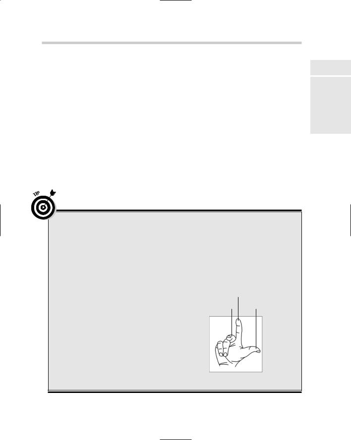
Right-hand rule for left-brained people
When you first look at the coordinate system in 3D, you may feel a little overwhelmed. After all, the UCS can be moved and rotated. So at times you may not know which way you are heading in the z direction or which way is the positive rotation around an axis. AutoCAD provides a method called the right-hand rule that you can apply when you need to figure out the direction of positive z and the positive rotation.
To identify the positive z axis with the right-hand rule, you place the back side of your right hand towards the monitor so that your palm is facing you. Take your thumb and point it in the direction of the positive x axis, then take your index finger and extend it out so it forms a right angle with your thumb. Make sure your index finger points in the direction of the positive y axis. Bend your middle finger towards you so it makes a right angle with your index finger. Your middle finger now indicates the positive direction of the z axis.
To identify the direction of positive rotation around an axis in 3D space, point your thumb on your right-hand in the positive direction of the axis and then curl your fingers. The direction that your fingers curl in indicates the positive direction of rotation around that axis.
Y axis
Z axis |
X axis |

294 Using the Coordinate System for 3D Drawing
Adjusting the UCS
AutoCAD offers a variety of different ways to create and save custom UCSs for future use. When you want to create a new UCS, you have some options as to how you want to create it, such as by selecting three points in the drawing to indicate origin, positive x, and positive y, or selecting an object. After you specify a new UCS, you can decide to save it for future use by giving it a name.
Commanding the UCS
The user coordinate system can be changed through the use of the UCS command. To make it easy to create a new UCS, AutoCAD offers a number of options that can be selected from the Tools menu under the New UCS submenu. The New UCS submenu offers a total of 11 possible selections, but AutoCAD provides a few that are not available from the submenu and are only available at the command line. We have listed some of the most commonly
used options of the UCS command to get you started. After the option is specified, follow the command prompts at the command line or the dynamic input tooltip. For more information on using the UCS options, refer to AutoCAD’s online Help system.
World: Changes the UCS to match the world coordinate system.
Face: Allows you to align the UCS to the face of a 3D solid.
View: Creates a new UCS by rotating the xy plane to being perpendicular to your current viewing direction.
3 Point: Allows you to specify a new origin for the UCS and designate the positive direction for both the x and y axes.
Using named UCSs
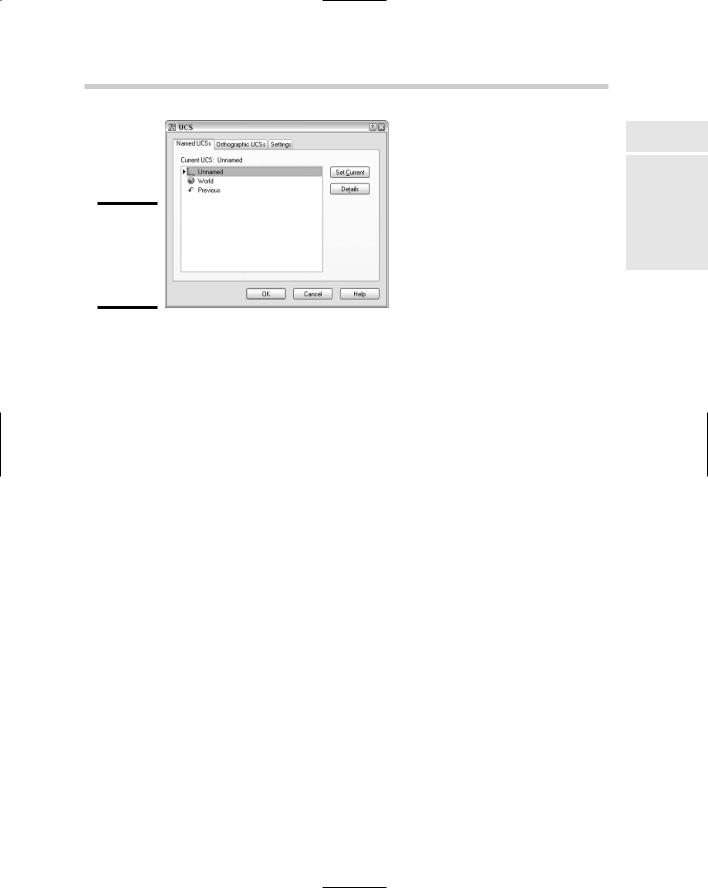
If you find yourself going back to a particular UCS to create or edit objects, you might consider saving the UCS for future use. To save a UCS that you created, you use the UCSMAN command which displays the UCS dialog box (see Figure 2-8). The UCS dialog box lets you save and restore named UCSs on the Named UCSs tab, customize the distance between the xy plane of the six orthographic coordinate systems (top, bottom, front, back, left, and right) on the Orthographic UCSs tab, and control some of the save and display settings for UCSs on the Settings tab.
The following procedure uses the Tools menu to start the UCSMAN command and save a custom UCS.
Using the Coordinate System for 3D Drawing 295
Figure 2-8:
Saving a custom UCS with the UCS dialog box.
1.Choose Tools Named UCS.
The UCS dialog box is displayed.
2.In the UCS dialog box, select Unnamed in the UCSs list.
The Unnamed UCS is the current UCS in the drawing and is listed at the very top of the list.
3.Right-click Unnamed and select Rename from the shortcut menu.
An in-place editor is displayed that allows you to change the UCSs name.
4.Type a new name for the UCS and press Enter.
The Unnamed UCS is renamed with the name entered.
5.Click OK.
The UCS dialog box closes and the UCS is saved in the drawing. To use a saved UCS, open the UCS dialog box and then select the saved UCS from the list and click Set Current.
Using the Dynamic UCS feature
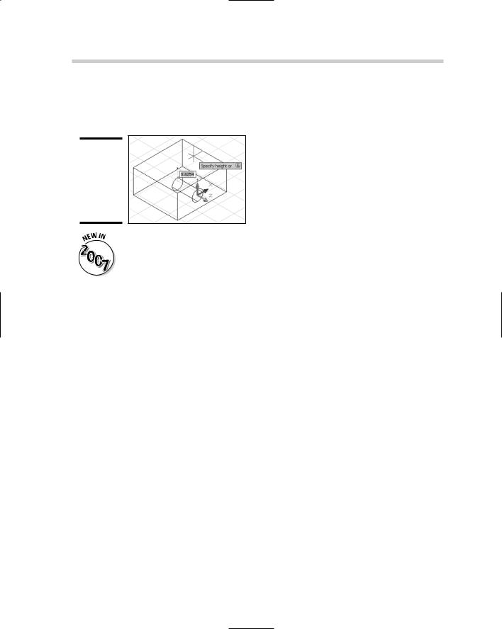
Setting up a UCS takes a bit of effort and can be distracting if you need to create one just to draw an object on the side of a 3D object. AutoCAD allows you to create a UCS on the fly using the Dynamic UCS feature. This feature can save you a great deal of time and is easy to toggle on and off. To toggle Dynamic UCS on or off, click the DUCS button on the status bar area. For example, when Dynamic UCS is turned on, you can start the CYLINDER command and position the crosshairs over one of the faces of a box to draw a hole in the box. The face that is being tracked is highlighted and when you
Book V
Chapter 2
UsingEnvironment
3D the
296 Using the Coordinate System for 3D Drawing
click to start drawing the cylinder, the UCS jumps to the face until you are finished with the command. Figure 2-9 shows the use of the Dynamic UCS in action.
Figure 2-9:
Dynamic UCS makes creating objects directly on solids easy.
Dynamic UCS is a new feature in AutoCAD 2007. This feature is not available in AutoCAD LT 2007.

Chapter 3: Viewing in 3D
In This Chapter
Establishing a different view of a 3D model
Orbiting around a 3D model
Navigating a 3D model
Adding a touch of visual style to a 3D model
In this chapter, we get immersed in 3D space as we explain how to navigate and view 3D models. AutoCAD and AutoCAD LT offer a number of ways to view 3D models in drawing files. These include basic preset views as well as much more sophisticated viewing tools, such as orbit and walk.
After you have the model displayed the way you want, you can apply a visual style or a shade mode to make the objects appear shaded or hidden on-screen.
Establishing a Different Point of View
AutoCAD offers a number of ways to view a 3D model, but AutoCAD LT offers only a few. AutoCAD LT offers a very basic set of navigation tools for viewing a 3D model; we cover all of them in this section.
Using preset views
Both AutoCAD and AutoCAD LT offer some standard preset views that can help you view different sides of a 3D model quickly. The presets include being able to view the 3D model from the top, left, and southeast. If the presets don’t offer what you need, you can use the Viewpoint Presets dialog box to get a little more control over the viewpoint.
Specifying a standard view preset
AutoCAD and AutoCAD LT have a total of 10 preset views. Six of these preset views are parallel to the current UCS — Top, Bottom, Left, Right, Front, and Back — and four of them are isometric views — SW Isometric, SE Isometric, NE Isometric, and SW Isometric. The presets are available from the 3D Views

298 Establishing a Different Point of View
submenu under the View menu on the menu bar, from the View Manager dialog box, or from the View toolbar. Select one of the presets to start the VIEW command and use the option that matches the selected preset.
Changing with the Viewpoint Presets dialog box
The Viewpoint Presets dialog box (see Figure 3-1) gives you more control over the viewing angle than the preset views do. To display the Viewpoint Presets dialog box, choose View 3D Views Viewpoint Presets. To change the angle, select either the Absolute to WCS or Relative to UCS option to set the viewing angle. Specify the angle from the x axis by entering a value in the From: X Axis text box or selecting the angle on the dial itself. After you set the x axis, specify the angle from the xy plane by entering a value in the From: XY Plane text box or from the dial on the right. Values above 0 allow you to look down on the model; values below 0 allow you to look up at the model as if you were below ground.
Figure 3-1:
The Viewpoint Presets dialog box.
Finding your way with the compass and tripod
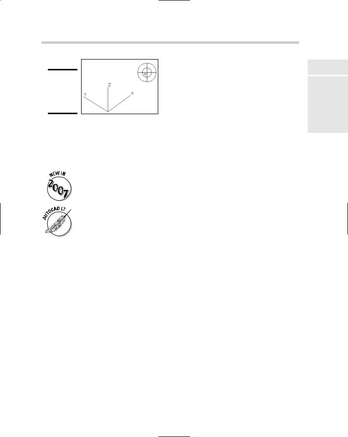
The preset views and the Viewpoint Presets dialog box are nice, but they do not provide a visual way to set a view. The VPOINT command allows you to see the current UCS via an axis tripod and a circular display known as the compass in the upper-right corner of the drawing window (see Figure 3-2). This allows you to specify the angle from the x axis and xy plane like the Viewport Presets dialog box does but is a little more visual and interactive. Although it is visually done on-screen rather than using a dialog box, it can still be a bit confusing. To select an angle above 0, keep the small crosshairs in the inner circle, which represents a positive z axis (the outer circle represents a negative z axis). Where the inner and outer circles meet is 0, or no change in the z axis direction.
Establishing a Different Point of View 299
Figure 3-2:
Using the tripod and compass for navigation.
Cameras
Cameras are similar to named views, with the exception that they have a graphical representation in a scene and can be updated via the Properties palette. Along with using the Properties palette, you can also edit a camera through the View Manager dialog box. The graphical representation is called a glyph, which allows you to manipulate the view of the camera with grips.
Cameras have been improved with AutoCAD 2007: They are now displayed and selectable in a drawing.
AutoCAD LT does not support the creation or use of cameras.
Creating a camera
To create a camera, you use the CAMERA command. To start the CAMERA command, select Create Camera from the View menu on the menu bar or on the View toolbar. As you create the camera, you specify a location for the camera and a target location. After the camera is created, you can change its name, location, height, target, lens, clipping, or switch to the cameras view. After the camera is created, the glyph is displayed in the drawing.
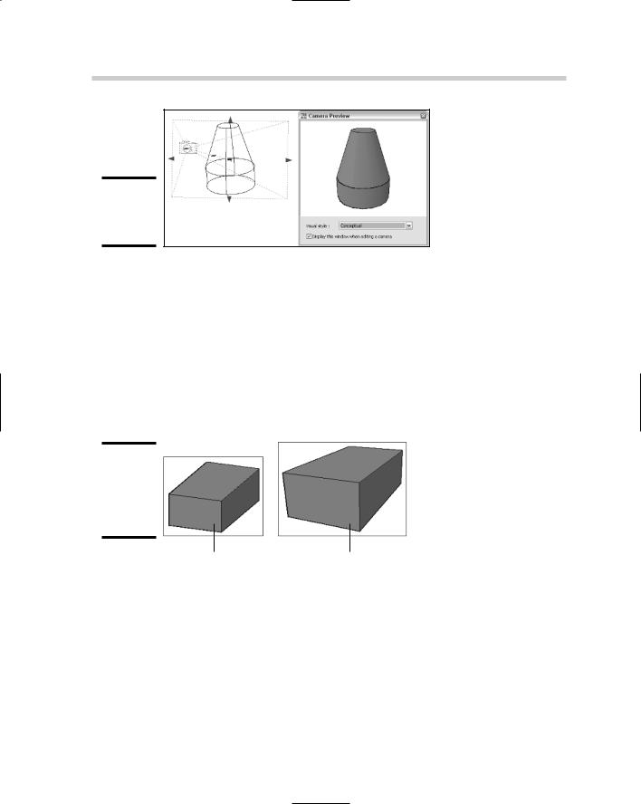
Adjusting the view of a camera
To adjust a camera, you select its glyph in the drawing and then adjust it using the grips that are displayed. Using grips, you can adjust the distance between the camera and target, along with the lens length of the camera. When a camera is selected, you should see the Camera Preview dialog box (see Figure 3-3) displayed on-screen, which lets you see what the camera is seeing without switching to the camera’s view. The Camera Preview dialog box gives you an idea of what is being seen through the camera. If the Camera Preview dialog box isn’t displayed when you select a camera in the drawing, right-click and select View Camera Preview on the shortcut menu.
Book V
Chapter 3
in Viewing 3D
300 Orbiting around a 3D Model
Figure 3-3:
Editing a camera in the scene.
Perspective versus parallel
AutoCAD and AutoCAD LT can display a 3D model in parallel view, which makes a 3D model appear flat and without depth, or in a perspective view, which makes a 3D model seem to disappear into the distance. Figure 3-4 shows a rectangle displayed in both parallel and perspective view. When you look at objects in real life, you see things in a perspective view. To enable perspective view in a drawing, type PERSPECTIVE at the command line or the dynamic ToolTip and enter a new value of 1. Perspective view is only available when a visual style or shade mode other than 2D wireframe is active. We talk about visual styles and shade mode later in this chapter.
Figure 3-4:
A rectangle in both parallel and perspective view.
Parallel view |
Perspective view |
Orbiting around a 3D Model
AutoCAD comes with many different commands that allow you to zoom in and around a 3D model. Being able to rotate the view around a 3D model allows you to quickly see things from a different angle and make the necessary edits. The ability to rotate the view around the 3D model is called orbiting, like what planets do around the sun. Orbiting is done along a circular
Orbiting around a 3D Model 301
path; the rotation point is different based on the orbit command you choose to use. To access the 3D orbit commands, from the menu bar, choose View Orbit and then one of the orbit commands.
AutoCAD LT does not support the 3D orbit commands.
Table 3-1 lists the three different 3D orbit commands available in AutoCAD.
Table 3-1 |
|
3D Orbit Commands |
|||
Icon |
Command |
Description |
|||
|
|
|
|
|
|
|
|
|
|
3DORBIT |
Constrained Orbit sets the target to a stationary point at the |
|
|
|
|
||
|
|
|
|
|
center of the objects that you are viewing when the 3DORBIT |
|
|
|
|
|
command is started. Dragging horizontally moves the camera |
|
|
|
|
|
|
|
|
|
|
|
along the current xy plane, and dragging vertically moves the |
|
|
|
|
|
camera along the z axis. |
|
|
|
|
|
|
|
|
|
|
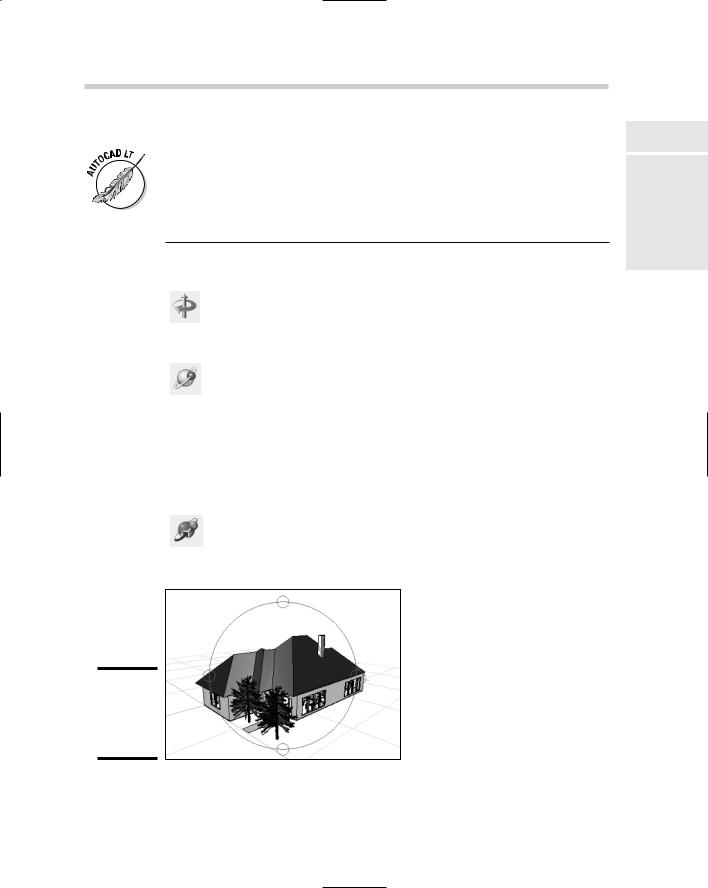
3DFORBIT |
Free Orbit sets the target of the view to the center of the arcball |
|
|
|
|
||
|
|
|
|
|
that is displayed. The arcball (see Figure 3-5) controls how the |
|
|
|
|
|
view is rotated around its center rather than the center of the |
|
|
|
|
|
|
|
|
|
|
|
objects you are viewing. Dragging inside the arcball allows you |
|
|
|
|
|
to freely rotate the model, whereas dragging on the outside of |
|
|
|
|
|
the arcball rolls the model perpendicular to the screen. Clicking |
|
|
|
|
|
and dragging in the left or right quadrants (smaller circles) |
|
|
|
|
|
causes the model to rotate around the vertical axis of the |
|
|
|
|
|
arcball, and clicking and dragging in the top or bottom quadrants |
|
|
|
|
|
(smaller circles) causes the model to rotate around the horizon- |
|
|
|
|
|
tal axis of the arcball. |
|
|
|
|
|
|
|
|
|
|
3DCORBIT |
Continuous Orbit is similar to Constrained Orbit in the way it |
|
|
|
|
||
|
|
|
|
|
works, except you can send the model into a continuous spin |
|
|
|
|
|
on-screen that lasts until you stop it. |
|
|
|
|
|
|
Figure 3-5:
The Free Orbit command is active.
Book V
Chapter 3
in Viewing 3D