

AutoCAD & AutoCAD LT All-In-One Desk Reference For Dummies (2006)
.pdf282 Entering Coordinates above the x,y Plane
Point filters
Point filters can be used for constructing coordinate values based on existing points on an object whether it is in 2D or 3D space. There are three point filters that are specific to 3D drafting. These point filters are xy, xz, and zy. Point filters can be typed in at the command line or dynamic input tooltip, selected from the Object Snap shortcut menu by pressing and holding down the Shift key while right-clicking, or right-clicking and choosing the Snap Overrides. Here is an example of using the LINE command to draw a line in 3D space using the xy point filter entry:
Command: line
Specify first point: specify a point or a coordinate value
Specify next point or [Undo]: type .xy and press enter of specify a point or a coordinate value
(need Z): specify a point or a Z height value
Object snaps
Object snaps are a great way to ensure that you have the precise point in the drawing that you want. AutoCAD has a toggle that controls whether the z height of the point you select using an object snap or the current elevation value is used. (We cover changing the current elevation later in this chapter.) To switch between these two, follow these steps:
1.Choose Tools Options.
The Options dialog box appears.
2.In the Options dialog box, click the Drafting tab.
3.Click the Replace Z Value with Current Elevation check box.
When you check the current elevation check box, AutoCAD substitutes the z height that was obtained with the object snap for the current elevation. When the check box is unchecked, the z height of the coordinate that is specified with the use of the object snap is used.
AutoCAD LT does not have the Replace Z Value with Current Elevation option.
Object snap tracking
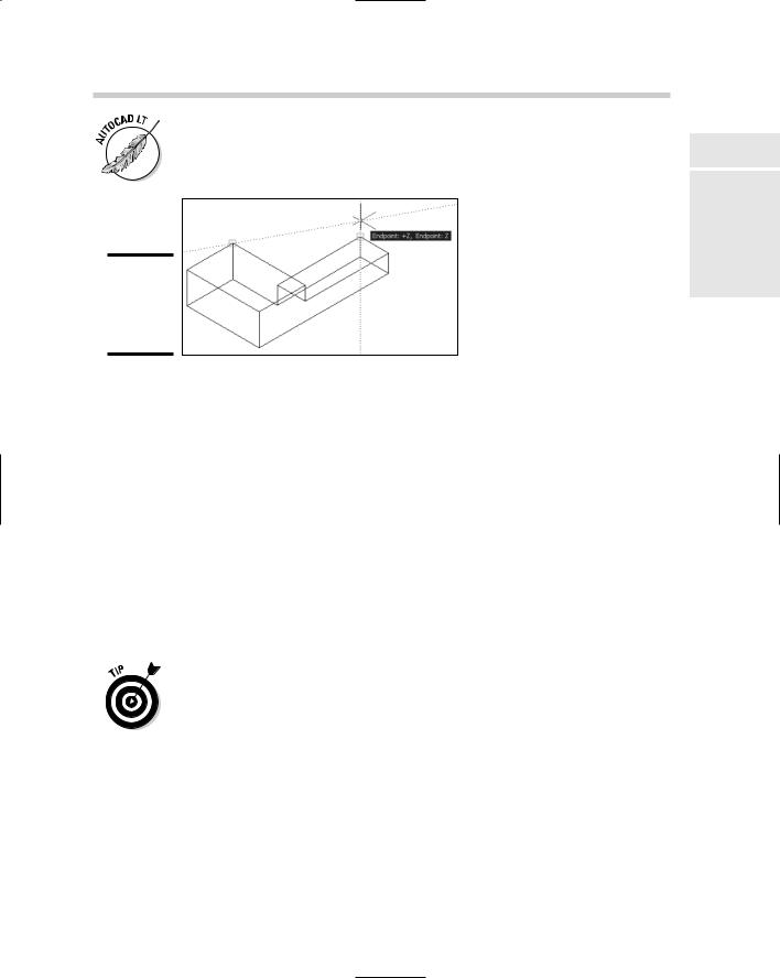
Object snap tracking can be used above the current x,y plane. Object snap tracking has been enhanced in AutoCAD 2007 to improve the functionality of being able to track in the z direction. When using object snap tracking in the z direction, AutoCAD provides feedback in the form of tooltips when you are moving in the positive or negative z direction. Figure 1-6 shows an example of the tooltip displayed in AutoCAD when using object snap tracking in 3D space.
Entering Coordinates above the x,y Plane 283
AutoCAD LT does support the use of object snap tracking in 3D space, but it doesn’t provide the same level of feedback that AutoCAD does.
Figure 1-6:
Object snap tracking in the Z direction.
Elevation . . . going up
Specifying a z height when entering coordinates is not the only way to draw objects above the x,y plane; you can specify a default z height for all new objects as they are created. If you are drawing a bunch of objects that need a specific z height, this can be a very efficient way to ensure they are placed at the correct height. You use the ELEV command to specify a new z height for new objects that are created. The value specified is used only if you don’t use object snaps; if you use object snaps, the z height of the object snap is used by default. See the previous section “Object snaps” for more information.
To set a new elevation value, type ELEV at the command line or the dynamic input tooltip and then enter a new elevation value at the Specify new default elevation <0.0000>: command prompt. Then, at the Specify new default thickness <0.0000>: command prompt, press Enter.
Instead of changing the current elevation, you can use a custom UCS (user coordinate system) to create objects at a specific elevation. We cover using the user coordinate system and the world coordinate system in the next chapter.
Book V
Chapter 1
the IntroducingDimension Third

284 Book V: 3D Modeling

Chapter 2: Using the
3D Environment
In This Chapter
Setting up AutoCAD for 3D
Understanding what the UCS icon is telling you
Changing the coordinate system for 3D drawing
The preceding chapter covers the three types of 3D models you can create with AutoCAD and AutoCAD LT, as well as how to enter coordi-
nates above the xy plane in the z direction. This chapter helps you get a grasp of the 3D environment in AutoCAD and AutoCAD LT. We take a look at some of the key settings and features that help you work efficiently with 3D models. Some of these settings are for getting the most out of your computer investment by enabling hardware acceleration if it is available, and some control the appearance of the grid, background color, and more in the drawing window.
One of the keys to becoming an efficient drafter with AutoCAD is understanding what the UCS icon is indicating, and in 3D drafting that is no different. The UCS icon provides you with information on which way is up or down in your model, and the direction of the x, y, and z axes. Not only can you get information from the UCS icon about the different directions that the axes are going in, but you can modify the coordinate system to draw 2D objects on a different plane. 2D objects are always drawn on the xy plane, so by changing the direction or elevation of the plane you can draw 2D objects on a new plane.
Setting Up AutoCAD for 3D
AutoCAD and AutoCAD LT offer various display, hardware, and drafting options that all play different roles when working with 3D. Properly configuring and understanding all these options can make things go more smoothly. Because AutoCAD LT doesn’t support the creation of surface and solid models, many of these options are not available. We point out the differences as we go along.
286 Setting Up AutoCAD for 3D
Orienting yourself in the drawing window
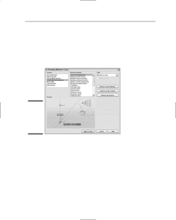
The drawing window is where you create, modify, and view your 3D models. Based on how you are viewing your model, the background color, grid display, and the crosshairs change in the drawing window. You can customize the display settings for the drawing window through the Drawing Window Colors dialog box (see Figure 2-1). The Drawing Window Colors dialog box can be displayed by clicking the Colors button under the Window Elements section on the Display tab of the Options dialog box.
Figure 2-1:
Customizing the appearance of the drawing window
for 3D.
In AutoCAD, you have the contexts 3D parallel projection and 3D perspective projection that are related to 3D drafting. In AutoCAD LT, you have only one context called hidden that is related to 3D drafting.
The following procedure explains how to adjust the colors of the Crosshairs interface element under the 2D model space content:
1.Choose Tools Options.
The Options dialog box is displayed.
2.In the Options dialog box, click the Display tab.
The Display tab is set to current.
Setting Up AutoCAD for 3D 287
3.On the Display tab under the Window Elements section, click Colors.
The Drawing Window Colors dialog box is displayed.
4.From the Context list, select 2D Model Space.
The Preview at the bottom of the dialog box updates to show the current colors that the interface elements are set to, and which interface elements are available.
5.From the Interface element list, select Crosshairs.
The Color drop-down list displays the current color, and the Tint for
X, Y, Z check box becomes enabled. The Tint for X, Y, Z option is used to give the crosshairs the colors of red, green, and blue to represent the different axes. The X axis is always represented by the color red, Y by green, and Z by blue. The tinting is by default enabled for the different 3D contexts.
6.Click Apply & Close.
The changes are saved and the Drawing Window Colors dialog box is closed.
7.Click OK.
The changes are saved and the Options dialog box is closed.
The Drawing Window Colors dialog box is an updated version of the Color Options dialog box.
Customizing crosshairs and dynamic input
You can customize the display of the crosshairs and dynamic input for working in 3D in AutoCAD only. These changes go beyond being able to change the size of the crosshairs or even color tinting of the different axes for the crosshairs. These options allow you to enable the display of labels on the crosshairs so you know which direction X, Y, and Z are without having to have the UCS icon displayed. You can also control whether the Z direction is indicated on the crosshairs as well. If you use Dynamic Input and manually enter points, you can control the display of a field for entering z-coordinate values. You can change these options under the 3D Crosshairs and Dynamic Input sections of the 3D Modeling tab in the Options dialog box.
The 3D Modeling tab of the Options dialog box is new and has a variety of options that affect the display of the crosshairs, dynamic input, UCS icon, creation and viewing of 3D objects, and the 3D navigation tools. The 3D Modeling tab is not available in AutoCAD LT.
Book V
Chapter 2
UsingEnvironment
3D the
288 Setting Up AutoCAD for 3D
Using workspaces to switch between 2D and 3D drafting
AutoCAD and AutoCAD LT come with a feature called Workspaces. Workspaces were introduced in AutoCAD 2006 and can play a role in efficiently switching between 2D and 3D drafting. You can create a workspace that displays the necessary tools that you need for a particular set of tasks. We talk about creating workspaces in Chapter 2 of Book IX.
A new workspace called 3D Modeling comes with AutoCAD 2007 but doesn’t come with AutoCAD LT 2007. This workspace displays the Dashboard palette; Tool Palettes window; and the Workspaces, Standard, and Layers toolbars. The layout tabs at the bottom of the drawing window are hidden.
Introducing toolbars and palettes for 3D
AutoCAD comes with a number of toolbars and palettes that contain 3Drelated tools for creating, editing, and navigating your drawings.
The Modeling toolbar contains tools for creating 3D solid objects, and some of the more common editing tools.
The Solid Editing toolbar contains tools that are used for editing individual faces and edges of a 3D solid.
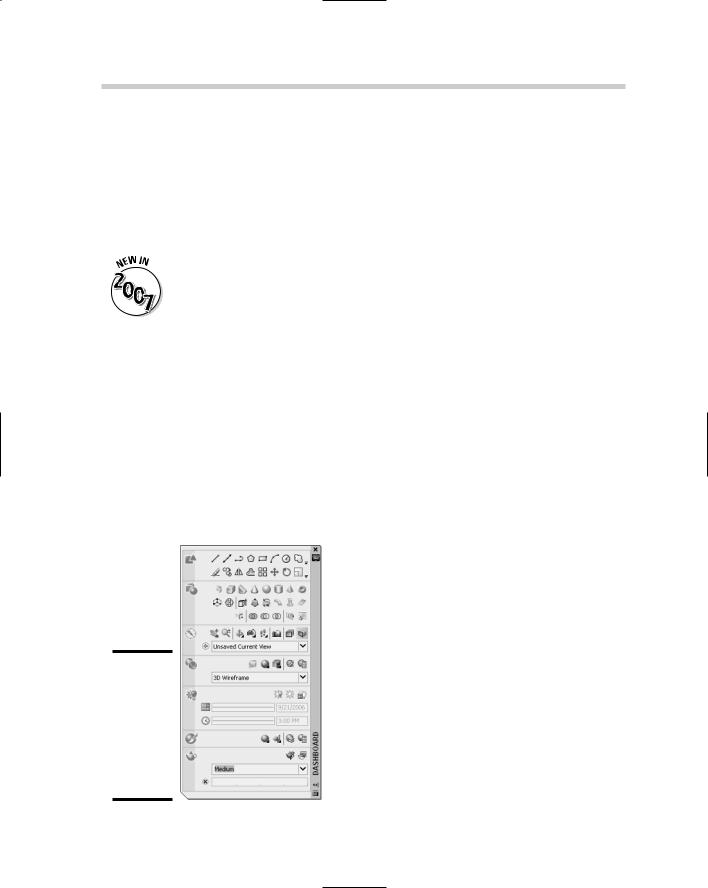
The Dashboard palette, shown in Figure 2-2, enables you to access many of the different commands for creating, editing, navigating, and visualizing 3D models.
Figure 2-2:
Dashboard allows for quick access to a variety of different 3D-related tools.
Setting Up AutoCAD for 3D 289
AutoCAD provides other toolbars and palettes that are useful for working with various different aspects of 3D in AutoCAD. Many of these palettes and toolbars are discussed in later chapters.
The Dashboard palette is new in AutoCAD 2007 and allows you to access both 2D and 3D drafting commands, along with other 3D features. Dashboard is not part of AutoCAD LT 2007.
Accelerating your hardware
AutoCAD can use either software or hardware acceleration to display a drawing to the screen. AutoCAD LT, however, does not support hardware acceleration. By default, AutoCAD uses hardware acceleration (because some graphics cards are not designed for CAD applications).
When you first start AutoCAD, the program evaluates your graphics card and determines whether it can use hardware acceleration. If it can, it informs you that your hardware is capable of this. At times your graphics card might not support all features using hardware acceleration, so AutoCAD tweaks its display settings a little to help optimize regenerations and overall display quality of the drawing window. This process is called adaptive degradation.
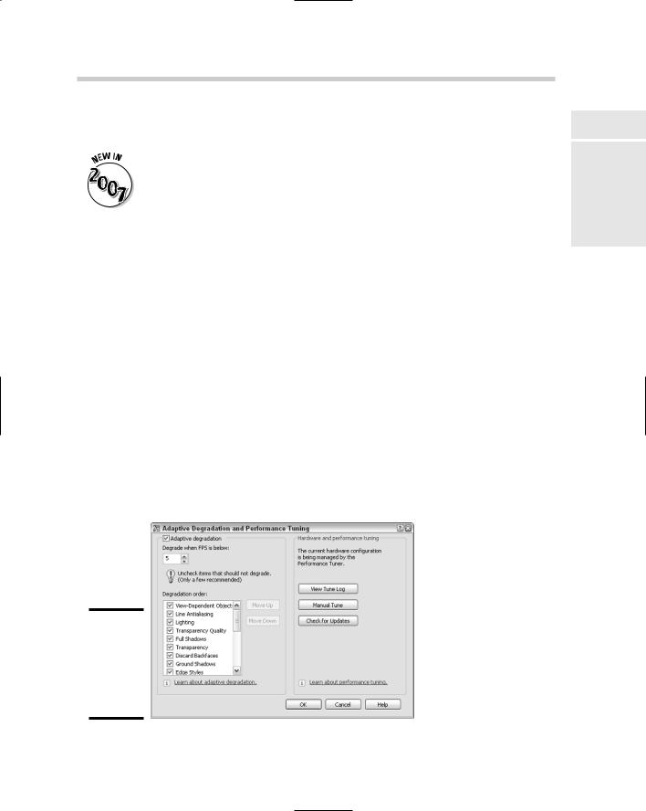
The Adaptive Degradation and Performance Tuning dialog box (see Figure 2-3) allows you to change the display options and toggle the use of hardware acceleration. To open the Adaptive Degradation and Performance Tuning dialog box, open the Options dialog box and click the Performance Settings under the 3D Performance section of the System tab. Click Manual Tune to toggle the use of hardware acceleration and options that are related to using hardware acceleration, such as Full Shadow and Smooth Line display.
Figure 2-3:
Performance tuning AutoCAD to get it to get rid of that extra regen.
Book V
Chapter 2
UsingEnvironment
3D the
290 Understanding What the UCS Icon Is Telling You
Understanding What the UCS Icon Is Telling You
The UCS icon is similar to a tour guide and helps you to stay on track as to which path you should be following. The UCS icon doesn’t tell you to stay with the tour and to keep up, but it does help you find the positive x, y, and z axes. It is important to know which direction these axes are going in for creating objects. It can get very frustrating when it doesn’t look like your line is being created when it actually is and you just don’t see it.
Orientating yourself with the UCS icon
The UCS icon can be strange at times depending on how you are viewing the drawing and whether you are in model or paper space. AutoCAD and AutoCAD LT display a different UCS icon for several situations; understanding these situations is necessary in order to help maximize the use of the user coordinate system, which we talk about later in this chapter. The UCS icon lets you know how the coordinates you type at the command line or dynamic input tooltip are affected. The appearance of the UCS icon is affected by the current visual style or whether the current view is displayed as hidden or shaded. We talk about visual styles, hide, and shade in Chapter 3 of this book.
Model space and 2D Wireframe visual style
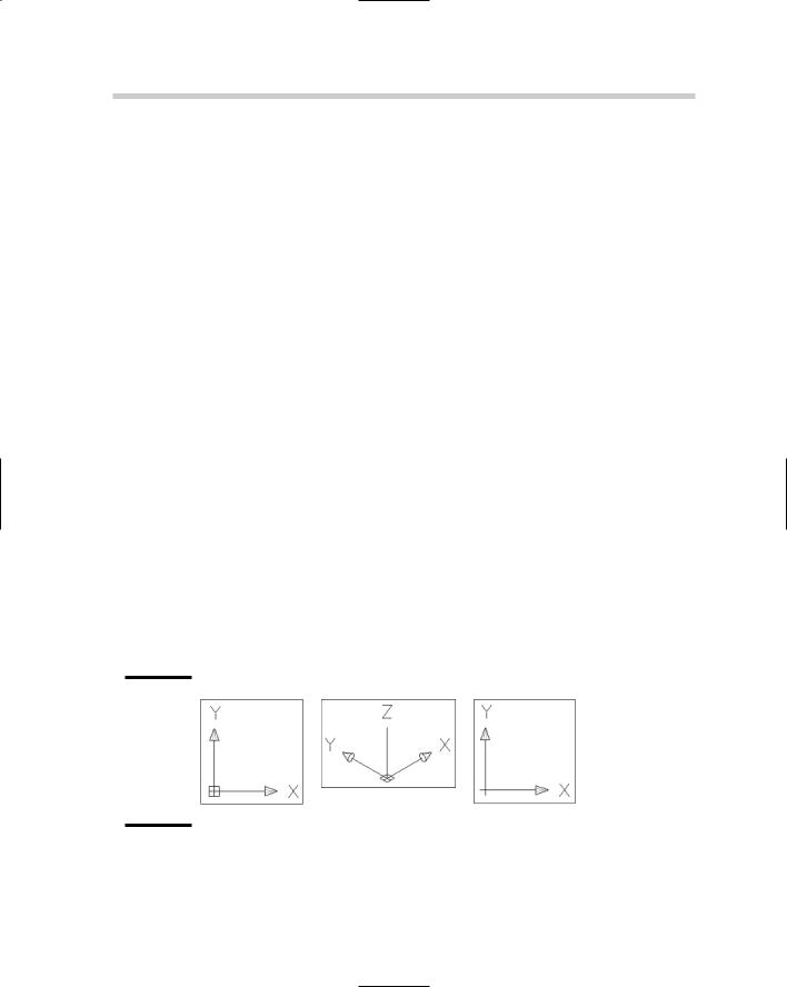
When you are looking straight on at the xy plane, the UCS icon shows the positive direction for the x and y axes. If the current view of the xy plane is from an angle like one of the preset isometric views, you will see the x, y, and z axes called out. Figure 2-4 shows the UCS icon as it would appear when looking at the xy plane straight on and from an angle. If you don’t see a box at the intersection of the x and y indicators, this informs you that you are not looking at the drawing from the world coordinate system.
Figure 2-4:
UCS icon displayed in model space with 2D Wireframe
visual style.
Understanding What the UCS Icon Is Telling You 291
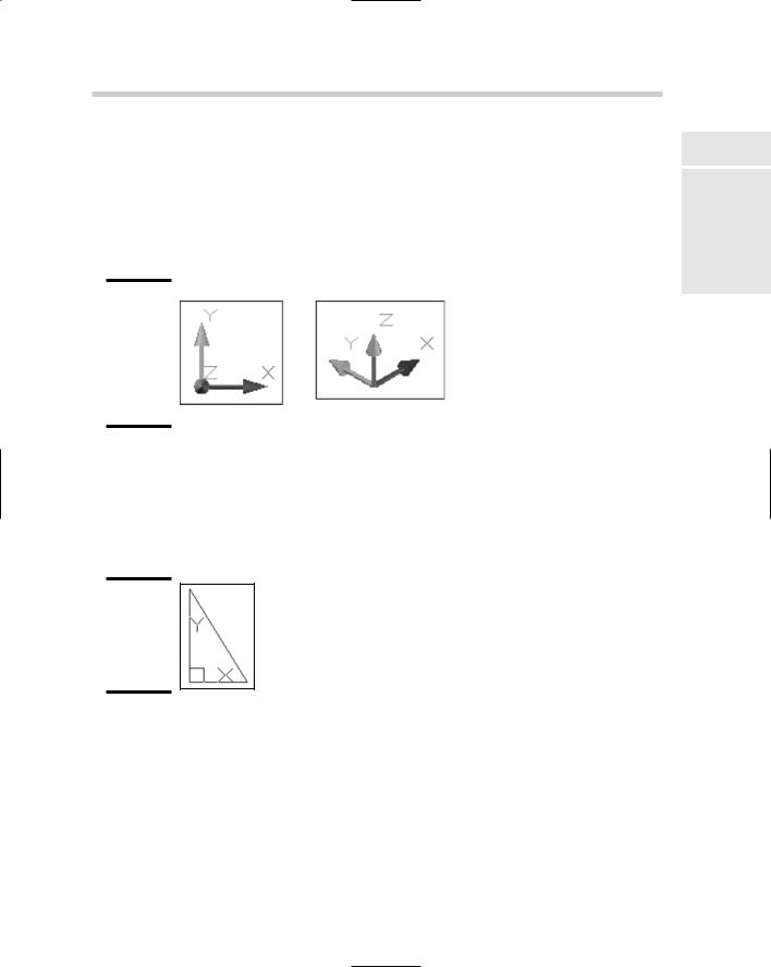
Model space and a 3D visual style
When you are looking straight on at the xy plane, the UCS icon shows the positive direction for the x and y axes, and the z direction coming toward or moving away from you. If the current view of the xy plane is from an angle like one of the preset isometric views, you will see the x, y, and z axes called out. Figure 2-5 shows the UCS icon as it would appear when looking at the xy plane straight on and from an angle.
Figure 2-5:
UCS icon displayed in model space with one of the 3D visual styles.
Paper space layout
Paper space layouts display a UCS icon that is a triangle and indicates the directions of the positive x and y axes only (see Figure 2-6). You cannot change the display angle of a paper space layout because the paper space layout is used to represent a virtual piece of paper.
Figure 2-6:
UCS icon displayed on a paper space layout.
Controlling the display of the UCS icon
The UCS icon by default has a 3D appearance to it and is displayed as a specific size, color, and location. You can tailor the display of the UCS icon with the UCS Icon dialog box (see Figure 2-7) and the 3D Modeling tab of the Options dialog box. To display the UCS Icon dialog box, choose View Display UCS Icon Properties.
Book V
Chapter 2
UsingEnvironment
3D the